Guitar Pedal Electronics

Drilling Guitar Pedal Enclosures

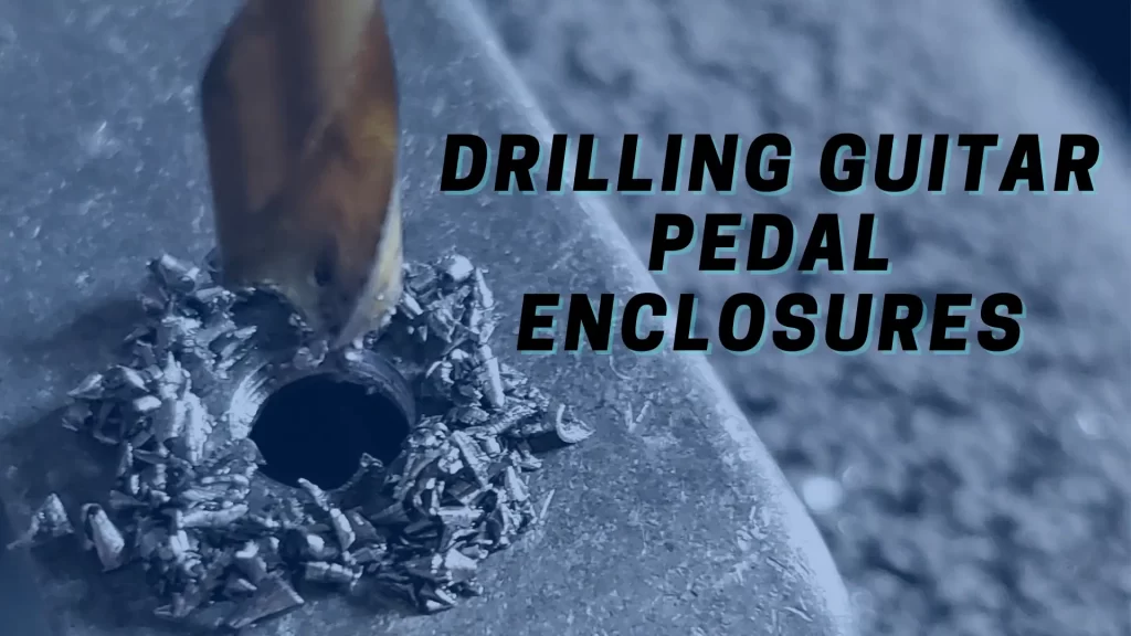
When designing or modifying your own effects, you’ll need to mount parts like switches, potentiometers, LED bezels, power jacks, input jacks, and output jacks. This requires you, the builder, to properly size, fit, and mount the component into the enclosure. In the following sections I go over my personal process for drilling guitar pedal enclosures. […]

Drilling Guitar Pedal Enclosures Read More »

Circuit 4 of 48: The Attenuator

[Last Updated: January 6, 2024] The Attenuator When you use a volume control knob on your guitar effect pedal you are most likely using a circuit called an attenuator. An attenuator is a circuit that decreases the amplitude of a signal. Attenuators are usually built with components called potentiometers. The Potentiometer A potentiometer (or pot,

Circuit 4 of 48: The Attenuator Read More »

Circuit 2 of 48: The De-Popper

Guitar effects design in 48 Circuits or Less. Number 2: The De-Popper

[Last Updated: January 4, 2023] Reviewing the True Bypass Circuit We introduced the True Bypass wiring scheme in Figure 1.1, shown again for your reference. When engaged, the input signal travels into the left side of the FX CIRCUIT block through switch SW1a. The output signal travels out of the right side of the circuit,

Circuit 2 of 48: The De-Popper Read More »

Circuit 1 of 48: The True Bypass

[Last Updated: January 3, 2024] What is True Bypass? The idea behind True Bypass wiring is simple: when bypassing a guitar pedal the signal should be routed directly from the input jack to the output jack with minimal interference. Nothing should get in the way of the guitar signal when the pedal is true-bypassed. The

Circuit 1 of 48: The True Bypass Read More »