
By: Dominic Sciarrino | Stompbox Electronics | Last Updated: March 12th, 2026
Today, we’re peeling back the curtain on Passive RC Filters! With just one resistor and one capacitor, you can build a circuit that selectively filters specific frequencies from an audio signal. That circuit is a passive RC filter, and it is one of the most fundamental building blocks in guitar effects pedal design. Once you understand how it works, you’ll start seeing it everywhere.
As a member of the Reverb Partner Program, eBay Partner Network, and as an Amazon Associate, StompboxElectronics earns from, and is supported by, qualifying purchases.
Disclaimer: Stompbox Electronics and/or the author of this article is/are not responsible for any mishaps that occur as a result of applying this content.
What is a Passive RC Filter?
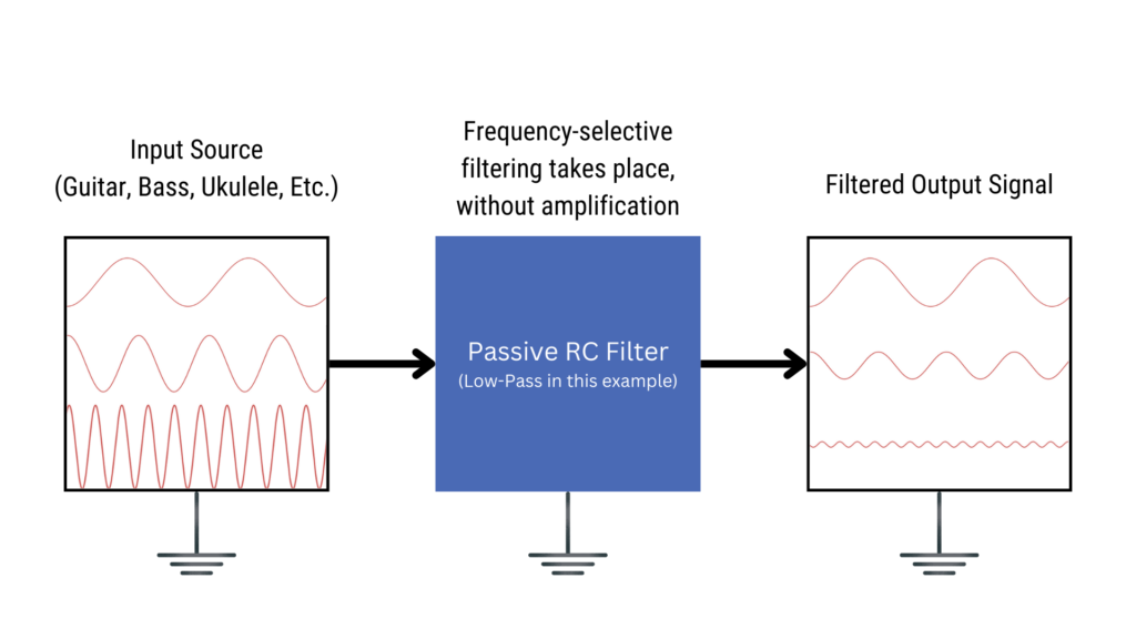
A passive RC filter is a circuit that uses a resistor (R) and a capacitor (C) to selectively attenuate certain frequencies while allowing others to pass through. The word passive is the key distinction here. Passive components like resistors, capacitors, and inductors do not require an external power source to function. Passive filters do not add gain. The most signal you can get out is equal or less than what you put in.
Active components, by contrast, do require power. Transistors and op amps are the two most common examples in guitar pedal design. When those components are used to build filters, the result is an active filter, which can amplify as well as attenuate. We’ll cover active filters later in the series.
The Voltage Divider Connection
If you’ve already read Circuit 3: The Voltage Divider, you already understand the foundation of every passive RC filter.
A voltage divider uses two resistors to produce an output voltage that is a fixed fraction of the input. The output is determined by the ratio of the two resistor values. Critically, it attenuates all frequencies equally. It doesn’t discriminate.
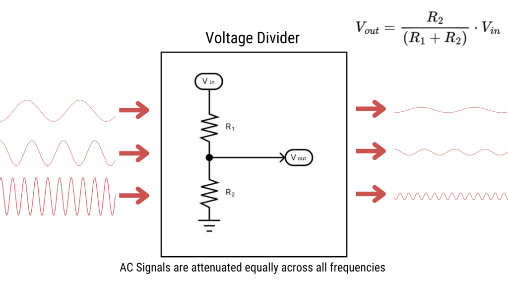
Now here’s the key step: replace one of those resistors with a capacitor. The capacitor has a property called capacitive reactance (Xc), which quantifies the opposition it presents to an AC signal (i.e. your guitar signal). Unlike a resistor, that opposition is frequency-dependent. At high frequencies, Xc is low and the capacitor looks nearly like a short circuit. At low frequencies, Xc is high and the capacitor looks nearly like an open circuit.
That frequency-dependent behavior is what turns a fixed voltage divider into a filter. The attenuation becomes selective, and which frequencies get cut depends on where the capacitor is placed in the circuit.
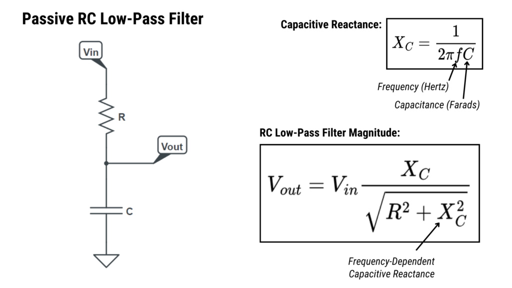
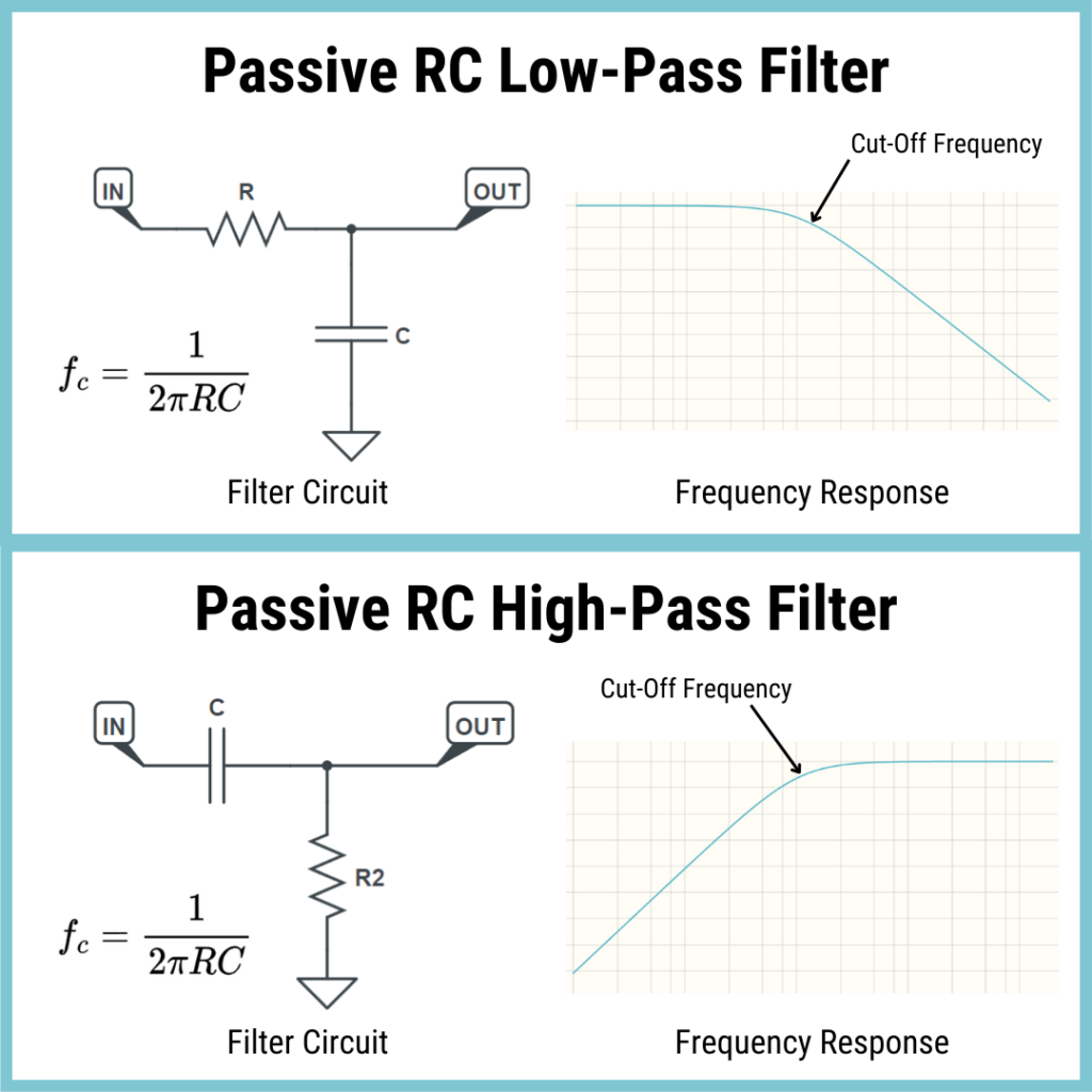
Figure 6.3 shows the RC low-pass filter in the same topology as the voltage divider circuit above, with R2 replaced by a capacitor. It shows how the output signal amplitude (Vout) can be calculated based on the input signal’s amplitude (Vin) and frequency (f).
The Cut-Off Frequency
Every low-pass and high-pass RC filter has a cut-off frequency (fc), marking the threshold at which the filter begins significantly attenuating the signal. Below the cut-off, a low-pass filter passes the signal with minimal change. Above it, the filter increasingly suppresses the signal. For a high-pass filter, that relationship is reversed.
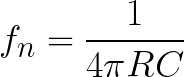
The cut-off frequency for both low-pass and high-pass RC filters is calculated with the same formula:
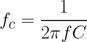
Where fc is the cut-off frequency in Hertz, R is the resistance in ohms, and C is the capacitance in Farads. The topology of the circuit (i.e. where the resistor and capacitor are placed) determines whether it is a low-pass or high-pass filter.
For band-pass and notch filters, there are two cut-off frequencies that define the upper and lower boundaries of the passband or stopband.
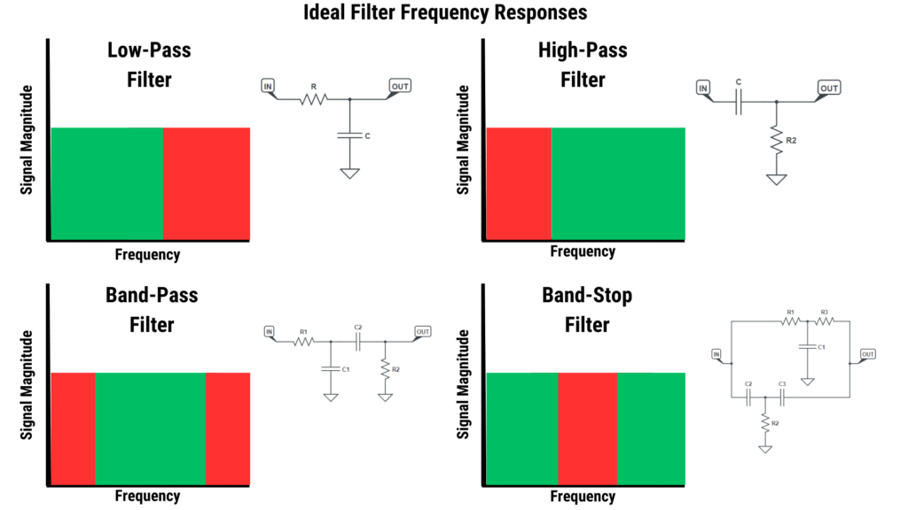
The Four Types of Passive RC Filters
There are four main types of passive RC filters. In this article, we will focus on low-pass, high-pass, and band-pass: the three types you’ll encounter most often in guitar effects design. Notch filters (also called band-stop filters) will be touched on and possibly covered in a future episode when the context is right.
| Filter Type | Behavior | Common Pedal Application |
|---|---|---|
| Low-Pass | Passes low frequencies, attenuates high frequencies | Tone controls, power supply ripple filtering |
| High-Pass | Passes high frequencies, attenuates low frequencies | Bass cut, treble bleed |
| Band-Pass | Passes a specific frequency band, attenuates above and below | Wah pedal resonant peak, midrange tone shaping |
| Notch (Band-Stop) | Rejects a narrow frequency band, passes all others | 60-cycle hum rejection, feedback elimination |
See Figure 6.5 below for the ideal frequency responses of all four filter circuits, along with their basic circuit topology.
The Low-Pass RC Filter
In a low-pass filter, the resistor is placed in series with the signal path, and the capacitor connects from the signal path to ground
Here’s the intuition using what we know about capacitive reactance:
- At low frequencies: Xc is high. The capacitor looks like an open circuit to ground. Signal passes through the resistor to the output with minimal loss.
- At high frequencies: Xc is low. The capacitor looks like a short to ground. High-frequency signals are diverted to ground before they reach the output.
See Figure 6.4 (top) below for a visual detailing the Low-Pass RC Filter and it’s frequency curve.
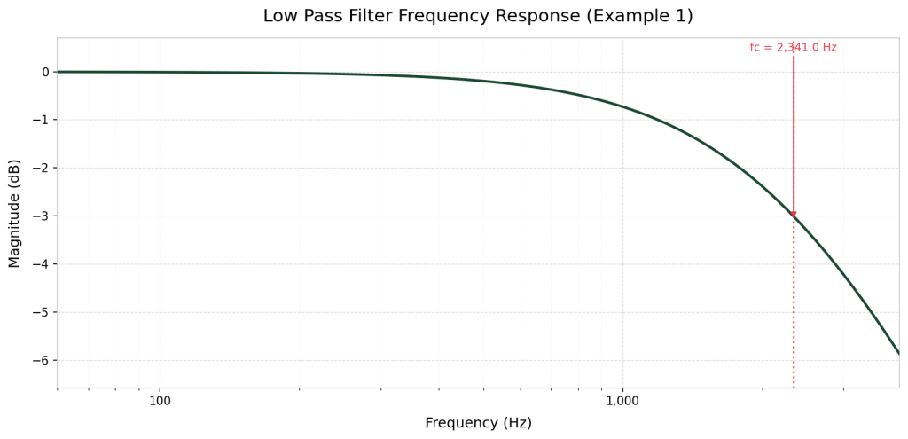
Low-Pass Worked Example: Treble Cut at 2.5 kHz
Let’s design a low-pass filter for a tone control application. The goal is to roll off the high end of a guitar signal starting around 2.5 kHz, a typical target for a “warm” treble-cut tone control.
Step 1: Choose a standard capacitor value. Start with 10nF (10 nanofarads), which is a common value for polyester film capacitors.
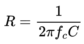
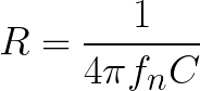
Step 2: Solve the cutoff frequency equation for resistance. R = 1 / (2 * 3.14159 * 2500 * 0.000000010) = 6,366 Ω.
Step 3: Select the nearest standard value. Using the E24 series, the nearest standard value above 6366 Ω is 6.8kΩ.
Step 4: Verify the actual cut-off frequency. Use Equation 6.1 to compute the actual cut-off: fc = 1 / (2 * 3.14159 * 6800 * 0.000000010) = 2,341 Hz.
Our actual cut-off is approximately 2,341 Hz, about 6.5% below the target. That’s well within the tolerance of standard passive components (typically ±5–10%) and perfectly acceptable for tone-shaping applications.
The High-Pass RC Filter
To flip the filter to high-pass, swap the positions of the resistor and capacitor. Now the capacitor is in series with the signal path, and the resistor connects to ground
The same reactance logic applies, now working in the opposite direction:
- At high frequencies: Xc is low. The capacitor passes the signal through to the output with minimal resistance.
- At low frequencies: Xc is high. The series capacitor presents high opposition, blocking low frequencies before they reach the output. They have nowhere productive to go
See Figure 6.4 above for the schematic and frequency response curve of a high-pass RC filter.
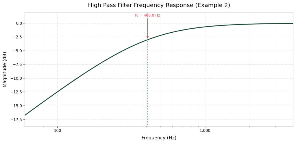
High-Pass Worked Example: Bass Cut at 400 Hz
A common technique in overdrives and distortions is to add a high-pass filter before the gain stage to cut the low end going into the amplification circuit. Without this, a gain stage can amplify bass frequencies aggressively, producing a muddy, flabby low end. Cutting at around 400 Hz cleans up the lower frequencies (of course, this isn’t universal – you’re encouraged to experiment).
Step 1: Choose a standard capacitor value. Start with 100nF (a standard polyester film cap).
Step 2: Solve for resistance. Just as you did for the low-pass, we need to calculate the resistance for our circuit: R = 1 / (2 * 3.14159 * 400 * 0.000000100) = 3,979Ω.
Step 3: Select the nearest standard resistor value. The nearest E24 value is 3.9kΩ.
Step 4: Verify. Use the frequency equation to get the actual cut-off frequency associated with the real-world component values. fc = 1 / (2 * 3.14159 * 3979 * 0.000000100) = 408 Hz.
Actual cut-off: 408 Hz – within 2% of target. Excellent.
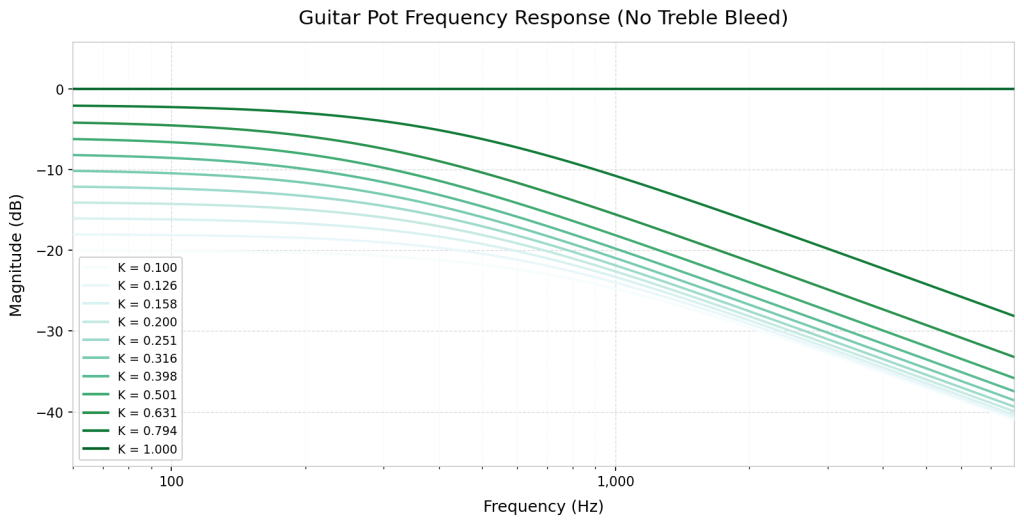
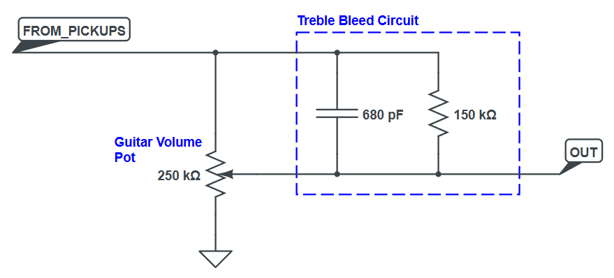
Real-World Application: Treble Bleed Circuit
One of the most recognizable passive high-pass filter applications in guitar electronics is the treble bleed circuit. When you roll back a guitar’s volume control, the high-frequency content tends to disappear disproportionately. The tone gets darker before it gets quieter. This happens because the volume pot interacts with the cable capacitance and pickup impedance in a way that preferentially loads down the treble frequencies as the pot’s resistance increases
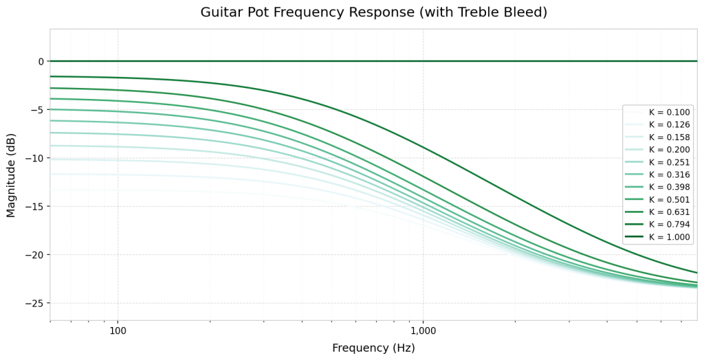
The fix is simple: place a small capacitor (sometimes with a series resistor) across the volume pot’s input and wiper lugs. As the pot is turned down, this RC high-pass network allows the high-frequency content to bypass the pot, preserving the tonal balance at lower volumes.
Typical treble bleed component values range from 100 pF to 1 nF for the capacitor and 100 kΩ to 300 kΩ for the series resistor, though optimal values depend on the specific pickup and pot combination.
The Band-Pass RC Filter
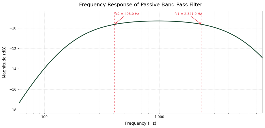
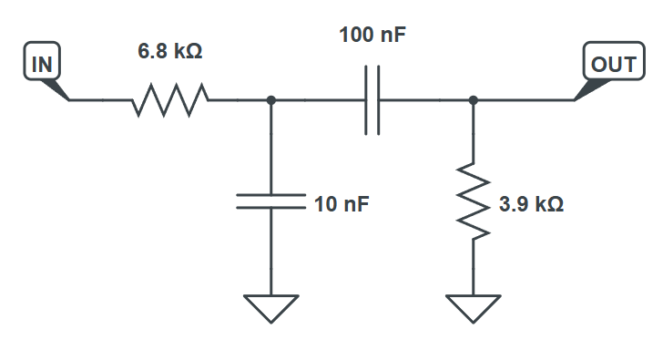
A band-pass filter passes a specific band of frequencies and attenuates everything above and below that band. In passive RC design, the simplest approach is to cascade a high-pass and a low-pass filter in series.
The high-pass stage cuts everything below the lower cut-off frequency. The low-pass stage cuts everything above the upper cut-off frequency. What remains between the two cut-offs is the passband.
- Set the high-pass cut-off to define the passband window.
- Narrow the gap between the two cut-off frequencies for a tighter, more selective filter.
- Widen the gap for a broader passband.
In practice, passive band-pass filters are limited by insertion loss: stacking two passive stages means the signal takes two attenuation hits. In real pedal designs, active band-pass filters using op amps are more common when precise frequency selection is required.
A Note on Notch Filters
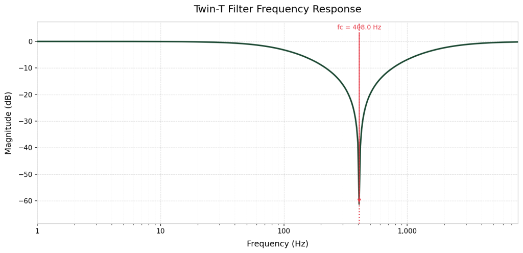
The fourth filter type, the notch filter (also called a band-stop filter), does the inverse of a band-pass: it rejects a narrow band of frequencies while passing everything else. A common use is rejecting 60 Hz (or 50 Hz) mains interference from an audio signal. The most common passive variation of a notch filter is called the Twin-T Notch Filter (Figure 6.13).
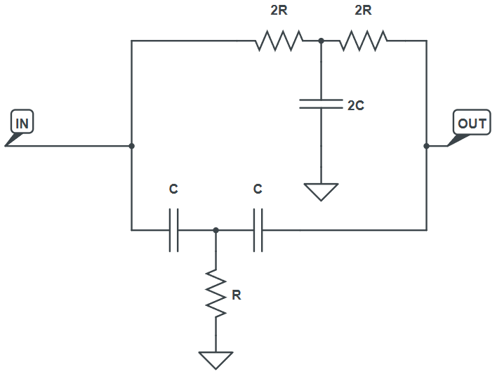
Contrary to the passive filter from above, the Twin-T uses a different equation for its cutoff (called the Notch Frequency) shown in Equation 6.3.
Notch filters are typically designed by first selecting the frequency you want to eliminate. You then choose an R and C combination where the cutoff frequency formula equals the target frequency.
Let’s use 408 Hz as our example Notch Frequency. This works out to a 1.95kΩ resistor and two 100nF capacitors for R and C, respectively. From the circuit diagram, we also need double those values – two 3.9kΩ resistors and a 200nF capacitor. The 1.95k resistor is not readily available, so we will use 1.8kΩ. Likewise, 200nF is not readily accessible, so we will increase that to 220nF.
The result of these component values is below:
Passive RC Filters in Guitar Pedal Context
You may have noticed in the demos that the filtered output is quieter than the unfiltered input. That’s not a flaw – it’s the nature of passive circuits. Passive filters do not add gain. They attenuate some frequencies relative to others, but the signal overall is only diminished, never amplified.
In real pedal designs, passive RC filters are almost never used in isolation on the signal path. They’re typically placed inside or after gain stages, where the gain compensates for the attenuation. A tone control resistor-cap combination sitting after a high-gain overdrive stage loses some level, but the signal is already so hot that the attenuation doesn’t register as a meaningful volume drop.
The same passive low-pass topology we built here shows up again in Circuit 8: The Power Supply Filter, where it’s used to filter ripple voltage from the DC power rail.


Guitar Effects Design in 48 Circuits or Less
The 48 Circuits or Less article series serves to close the gap between DIY guitar effects design and guitarists interested in the craft by uniquely curating the most important aspects of DIY guitar effect circuit design. This post is part of the 48 Circuits or Less series. View more articles in this series here.
Meet the Author:

Hi, I’m Dominic. By day, I’m an engineer. By night, I repair and modify guitar effects! Since 2017, I’ve been independently modifying and repairing guitar effects and audio equipment under Mimmotronics Effects in Western New York. After coming out with a series of guitar effects development boards, I decided the next step is to support that community through content on what I’ve learned through the years. Writing about electronics gives me great joy, particularly because I love seeing what others do with the knowledge they gain about guitar effects and audio circuits. Feel free to reach out using the contact form!
The Tools I Use
As a member of Amazon Associates, Stompbox Electronics earns and is supported by qualifying purchases.


