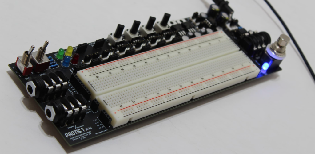
PROTIS 1™ MINI Guitar Effects Development Board
The PROTIS 1™ MINI is a compact prototyping solution for DIY pedal builders and enthusiasts.
- Organize and stream-line your design experience.
- No need for constructing repetitive power and input/output wiring.
- Expand your ability to test expression pedal or TRS MIDI applications.
PROTIS 1™ MINI Features
- 830-point breadboard prototyping space
- Input and Output jacks for guitar and amplifier testing
- On-board positive and negative power options
- True Bypass switching for easy on/off floor testing with other effects chains
- Four (4) on-board potentiometers and two (2) toggle switches
- Auxiliary 1/4″ Jack for expression pedal or MIDI applications
- Propped up from the bench surface with six (6) rubber feet
- [Optional] 18VDC Power Supply
- [Optional] Male-Male prototyping jumper wires
I. Power
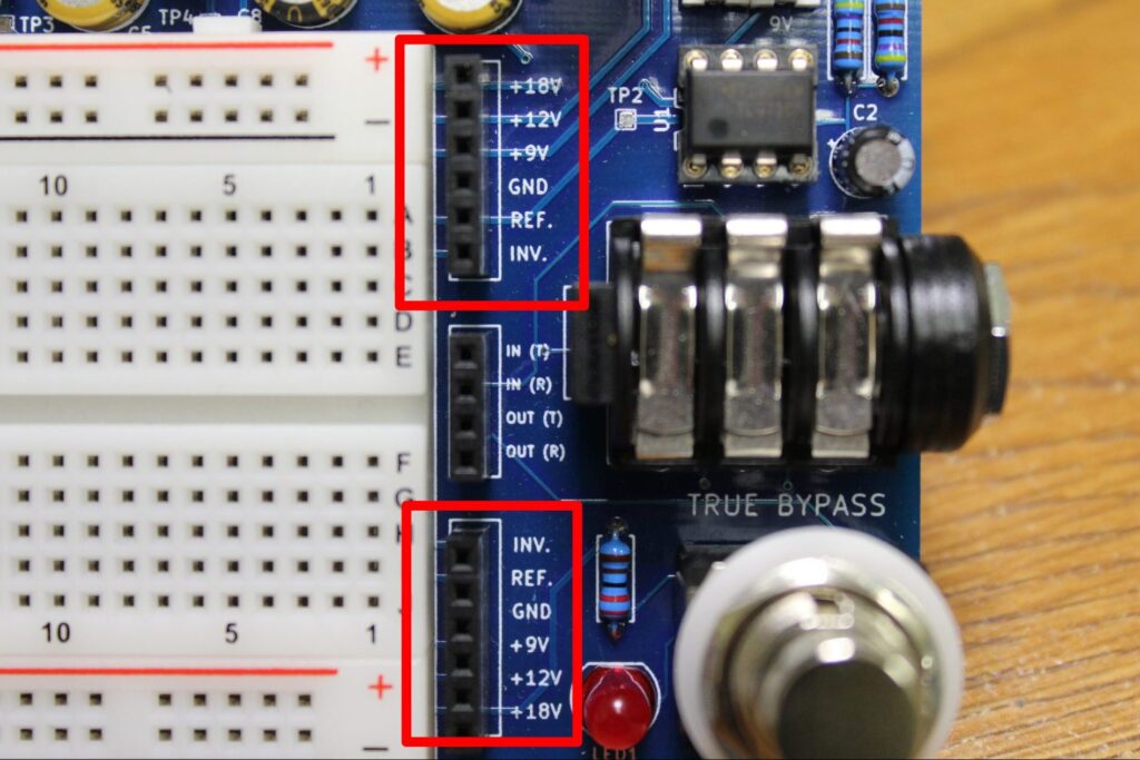
The PROTIS 1™ MINI hosts three (3) power rails (+18V, +12V, and +9V), the latter two are made live by removable jumpers.
The +12V and +9V rails have their inverted counterparts (-12V and -9V) which are made available by their respective jumpers.
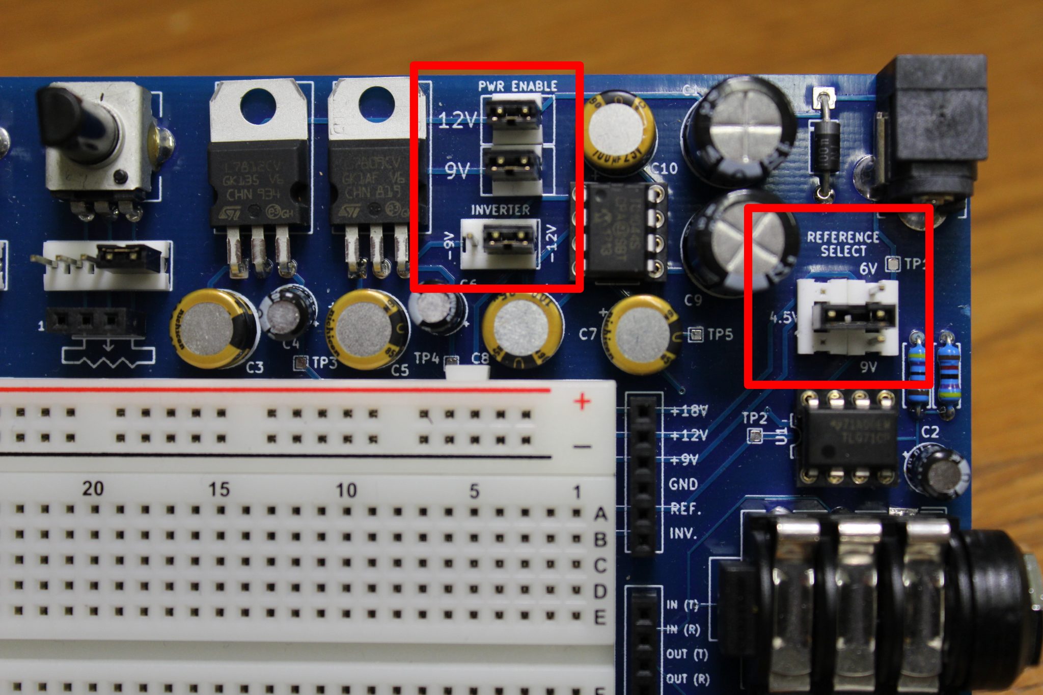
Half-voltage DC biasing for single-supply circuits is accessed by configuring the REFERENCE SELECT jumpers.
Power is easily accessible from the female headers to the right of the breadboarding space.
***Recommended Power Supply: +18V DC power supply, 500mA. This can also be provided by 18VDC pedal power bricks, like the Voodoo Labs ISO 5, for example.
II. Signal Flow
Signal flow is identical to how it works in most pedals: right to left! The guitar’s input signal is applied to the right-side 1/4″ jack and the output is taken from the left-side 1/4″ jack.
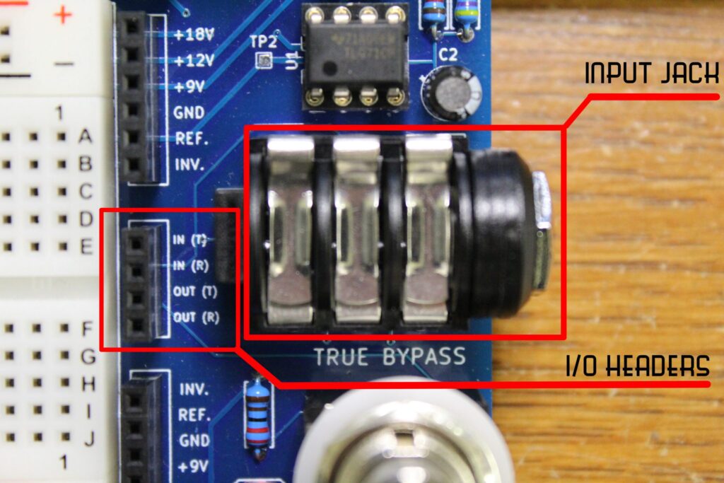
A 3PDT footswitch switch in the lower-right hand corner of the board carries out True-Bypass operation. The LED next to the switch serves as an indicator for when the breadboarded circuit is “engaged” (ON) or “disengaged” (OFF).
When the circuit is “ON” the input and output jack’s Tip signals are routed to the Signal I/O headers on the left and right sides of the breadboarding space. The input guitar signal and output FX signal can be connected to the breadboard using jumper wires from the I/O headers.
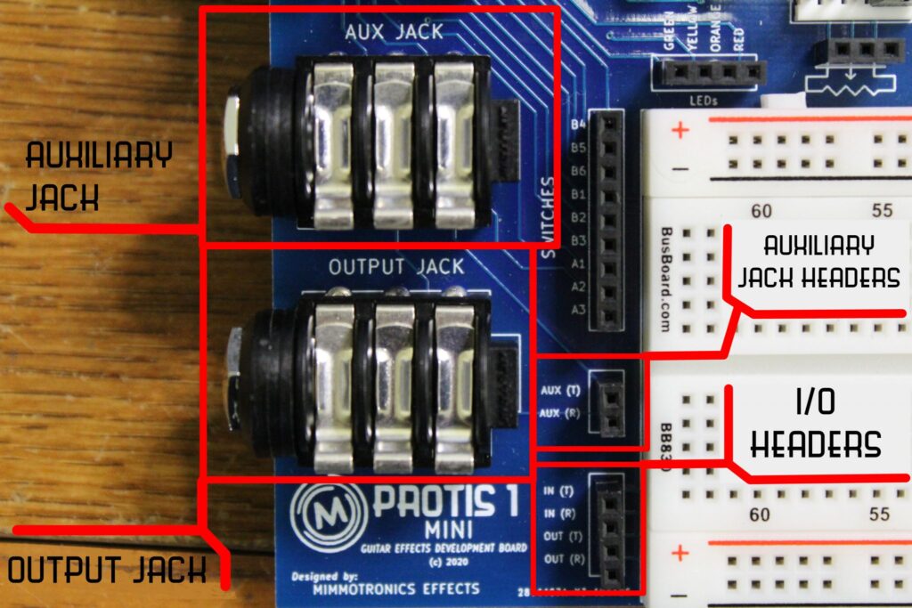
Stereo effects can also be developed using the PROTIS 1 MINI by utilizing the “ring” connections on the I/O headers. Do note, however, these ring connections are not switched on or off by the 3PDT switch, only the tip connections.
III. Potentiometer Interface
Four (4) On-Board Potentiometers are available for use on the PROTIS 1 MINI:
- 1 kOhm Linear B
- 10 kOhm Linear B
- 100 kOhm Linear B
- 1 MOhm Linear B
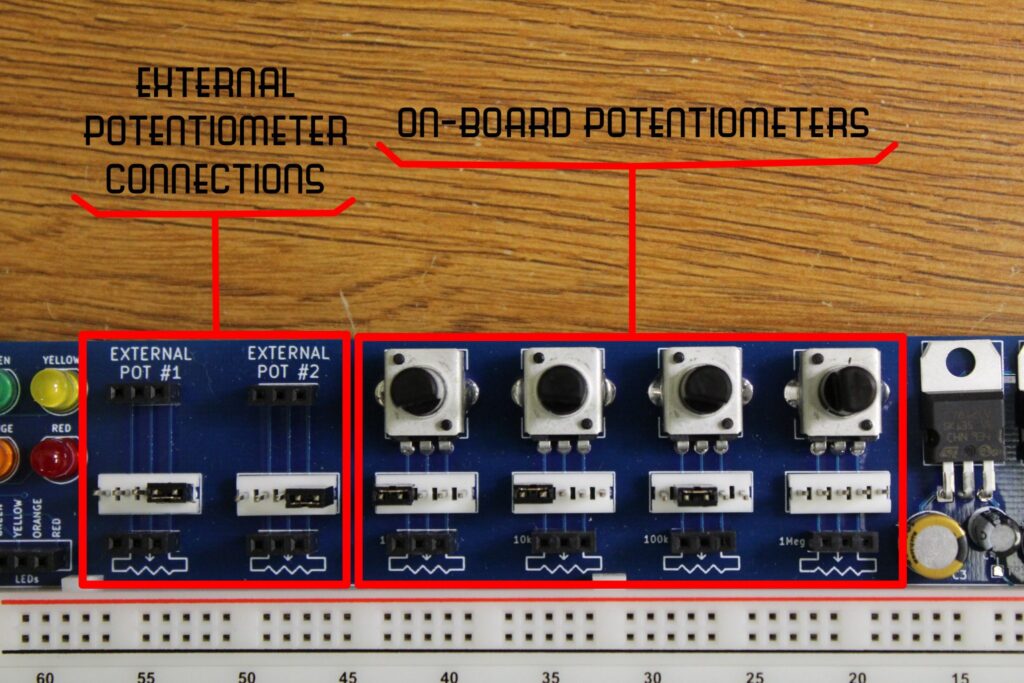
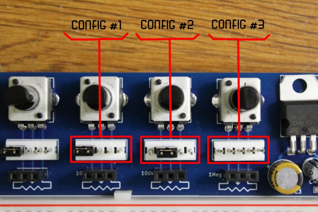
Pot Interface Jumper Configurations allow you to minimize the wiring needed for using potentiometers.
Two sections are reserved for the Connection of External Potentiometers in the case that the PROTIS 1™ MINI does not house the value you need for the circuit at hand.
IV. Auxiliary Devices
The PROTIS 1™ MINI offers three (3) auxiliary devices, including:
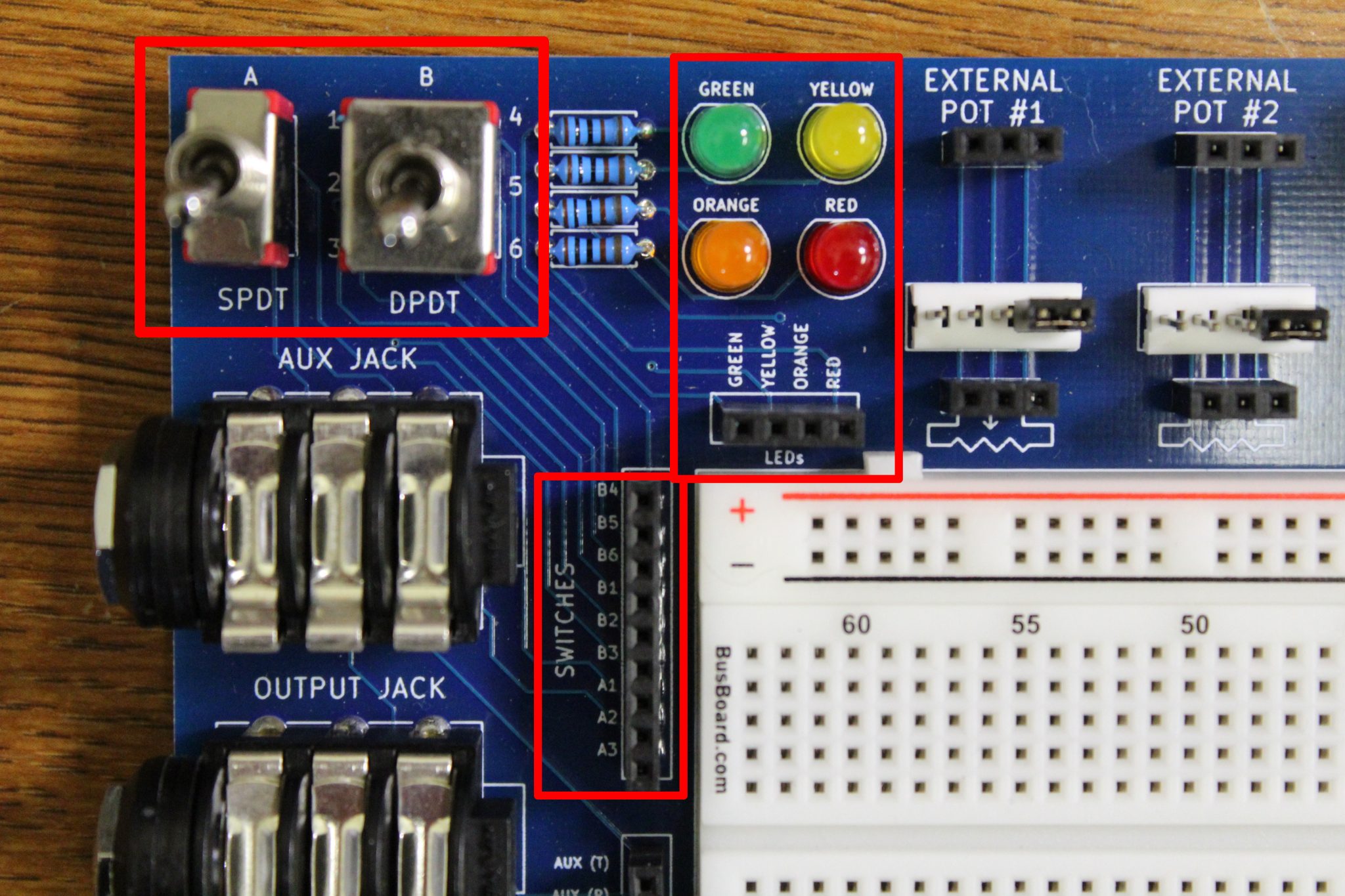
- Four (4) LEDs: Green, Yellow, Orange and Red (current-limited with a 1k-Ohm resistor)
- An SPDT ON-ON toggle switch
- A DPDT ON-OFF-ON toggle switch
- An Auxilary 1/4″ Jack: for expression pedal or MIDI applications
Each of these devices are accessed by the corresponding headers along the left side of the breadboard prototyping space.