
[Last Updated: February 27th, 2026]
As a member of the Reverb Partner Program, eBay Partner Network, and as an Amazon Associate, StompboxElectronics earns from, and is supported by, qualifying purchases.
Disclaimer: Stompbox Electronics and/or the author of this article is/are not responsible for any mishaps that occur as a result of applying this content.
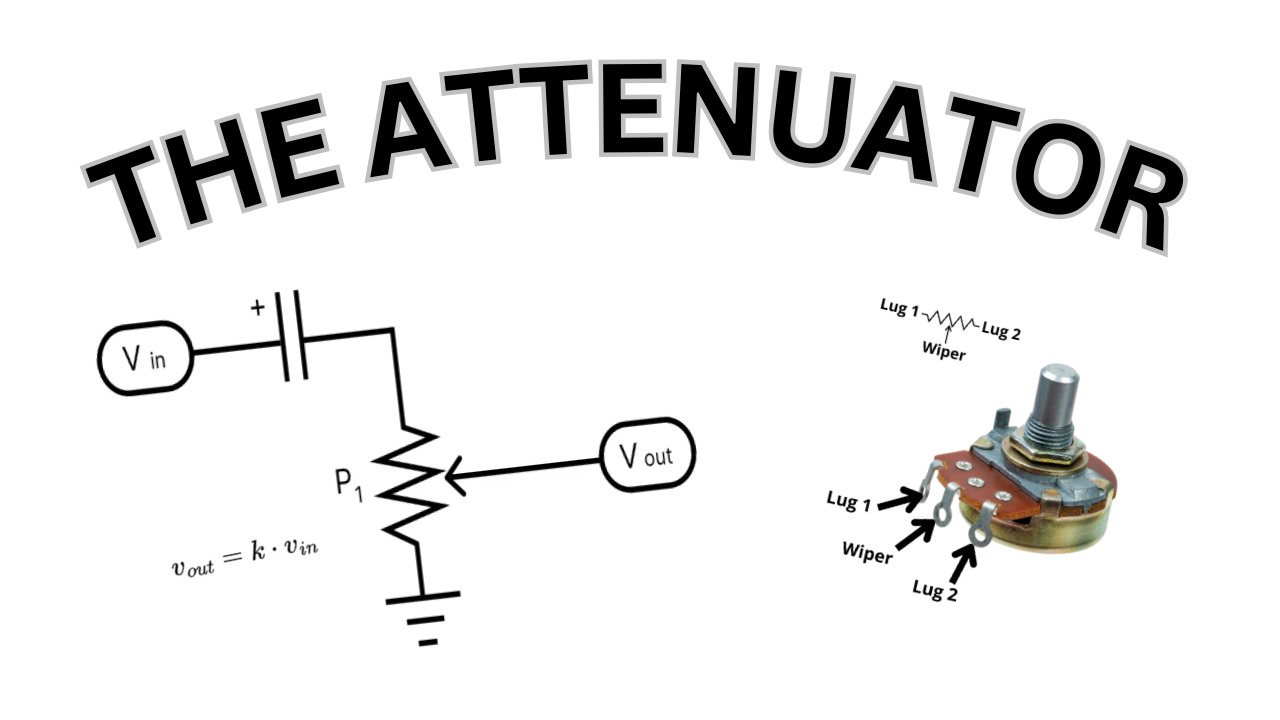
The Attenuator
When you use a volume control knob on your guitar effect pedal you are most likely using a circuit called an attenuator. An attenuator is a circuit that decreases the amplitude of a signal. Attenuators are usually built with components called potentiometers.
The Potentiometer
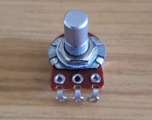
A potentiometer (or pot, for short) is a three-lug device that allows you to dial in a variable resistance.
In Figure 4.2, Lug 1 and Lug 2 connect to opposite ends of a resistive material while the middle lug connects to a wiper. This wiper slides across the internal resistive material, allowing you to make contact at different points.

The Attenuator Circuit
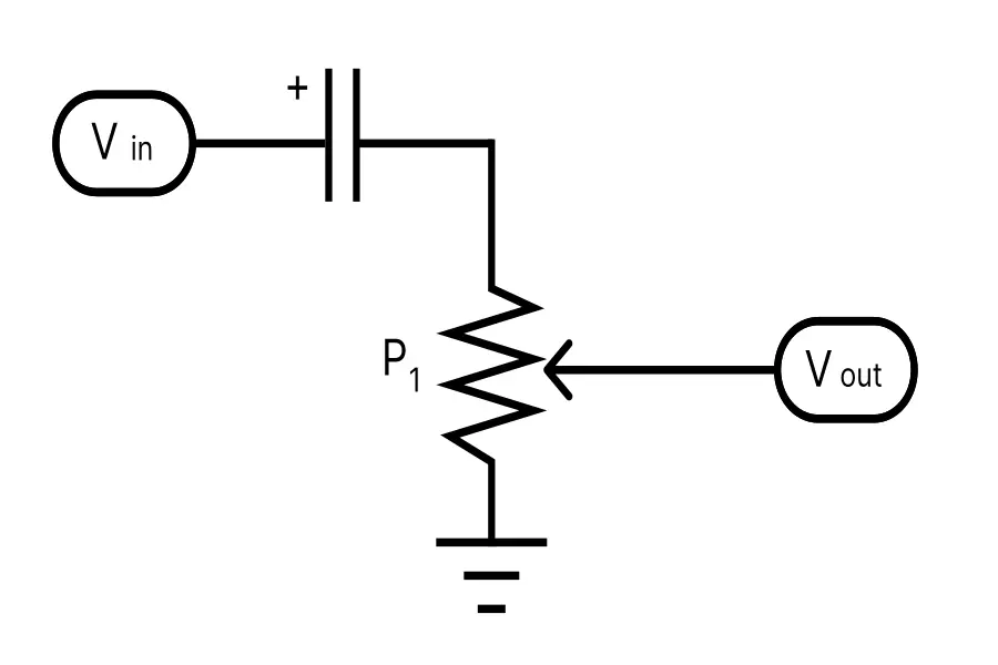
There are three main connections you need to make to build an attenuator circuit. Using Figure 4.2 above for reference:
- Connect Lug 1 to 0V (ground)
- Apply the input signal (Vin) to Lug 2
- Take the output signal (Vout) the Wiper
Figure 4.3 (below) shows an attenuator, except I’ve added a capacitor in series with the input signal.
Capacitors help to block DC voltages from entering different areas of a circuit. In this case, it prevents DC voltage that may be superimposed on the input signal from entering our attenuator. The technical term for a capacitor used in this way is blocking capacitor.
The attenuator works in the following way:
- When the wiper is at the top, 100% of the signal reaches the output.
- Turning the wiper downwards results in increasing attenuation.
- When the wiper reaches the bottom the output becomes grounded and, therefore, fully attenuated (muted).
The Attenuator Equation
Mathematically, if we use k to represent the rotation of the wiper, we can relate the input and output of the circuit with Equation 4.1.
In this case, ‘k’ travels from 0.0 to 1.0, where 0.0 represents the position at Lug 1 and 1.0 represents the position at Lug 2 (following the terminology in Figure 4.2).
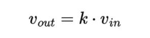
If the wiper is at the halfway point between the two lugs then k = 0.5 and the amplitude of the input signal is halved at the output.
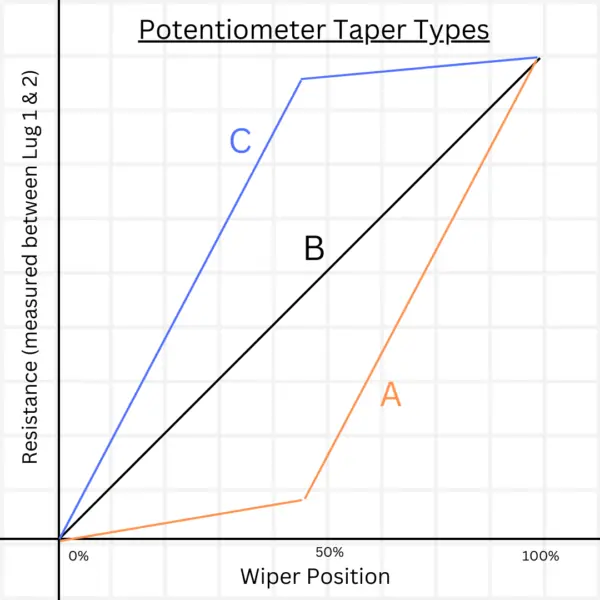
Types of Potentiometer Tapers
Potentiometers have a property called taper. There are three main types of taper:
- Type A: Logarithmic Taper (Log)
- Type B: Linear Taper
- Type C: Inverse Logarithmic Taper (Inverse Log)
Essentially, the taper of a potentiometer changes how the attenuator equation looks. Equation 4.1 is for linear tapers only and is represented by the B line in Figure 4.4 below. Lines A and C roughly depict how logarithmic and inverse logarithmic tapers behave.
Attenuator Circuit Parts List
You only need two components to build an attenuator (a.k.a. volume control): a potentiometer and a capacitor.
| Parts | Qty |
|---|---|
| Potentiometer | 1 |
| Capacitor | 1 |
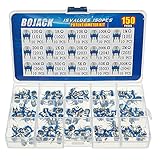
There will be multiple occassions where you’ll need these types of components, so it’s best to purchase them in bulk in the form of an assorted kit. The Bojack kits found on Amazon are great. Disclaimer: as an Amazon affiliate, Stompbox Electronics earns from and is supported by qualifying purchases.
That said, I’ve purchased the Bojack kits myself and they have been extremely useful to have around when prototyping circuits for this article series.


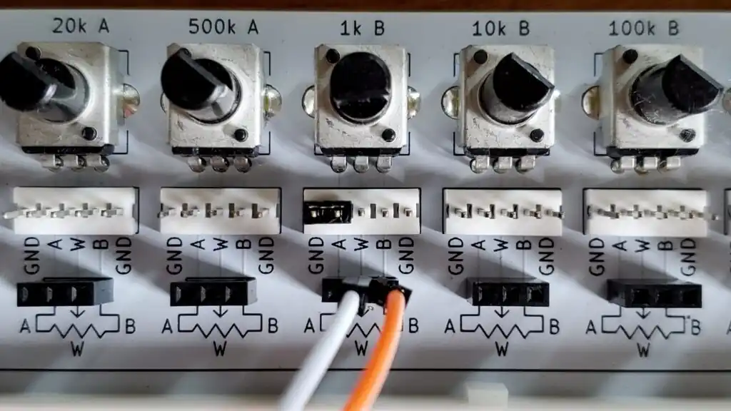
Volume Control on the PROTIS 1
The PROTIS 1 Development Board comes with six onboard potentiometers. You can build the Attenuator circuit using these potentiometers and some jumper cables.
Simply jump the “A” terminal of the potentiometer to ground (GND) with the included jumper. Then, connect the wiper (W) to the output (OUT TIP). Finally, connect the B lug to the input (IN TIP).
For more information on how to use the potentiometer interface on the PROTIS 1, see this supporting article.
Resources
[1] Code Effects – Potentiometers and Guitar Effects, (C)2015-2022
[2] Potentiometer Calculator
[3] Potentiometer Taper
[4] R.G. Keen The Secret Life of Pots, (C)1999
Related Posts
Meet the Author:

Hi, I’m Dominic. By day, I’m an engineer. By night, I repair and modify guitar effects! Since 2017, I’ve been independently modifying and repairing guitar effects and audio equipment under Mimmotronics Effects in Western New York. After coming out with a series of guitar effects development boards, I decided the next step is to support that community through content on what I’ve learned through the years. Writing about electronics gives me great joy, particularly because I love seeing what others do with the knowledge they gain about guitar effects and audio circuits. Feel free to reach out using the contact form!
The Tools I Use
As a member of Amazon Associates, Stompbox Electronics earns and is supported by qualifying purchases.


