
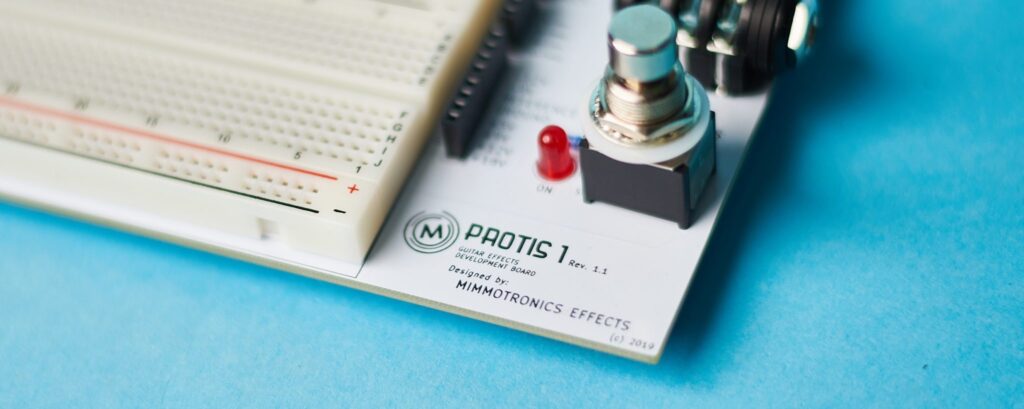
The PROTIS 1 sports a convenient potentiometer, or “pot,” interface for fast and easy breadboard wiring. In this post we’ll explore what this interface looks like and how to utilize it for building the circuits that require them.
Disclaimer: Stompbox Electronics and/or the author of this article is/are not responsible for any mishaps that occur as a result of applying this content.
Preliminaries: Potentiometer Operation
A basic potentiometer has three connection points. We will call them:
- Lug 1
- Wiper
- Lug 2
Between Lug 1 and Lug 2 there is a fixed resistance. The Wiper is a sliding or rotating contact that forms a varying resistance between each of the two other lugs. The resistance between the Wiper and Lug 1, for instance, grows as the Wiper position is rotated further away from Lug 1.
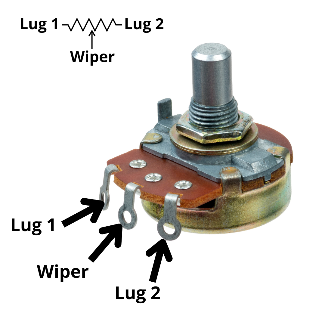
Additionally, the resistance between the Wiper and Lug 1 shrinks as the Wiper position moves toward Lug 1. The same happens for Lug 2 in the reverse direction.
Taper
The potentiometer’s taper is another important specification. A linear taper signifies a linear change in resistance as the Wiper sweeps across the resistive contact, while a log taper signifies a logarithmic change in resistance.
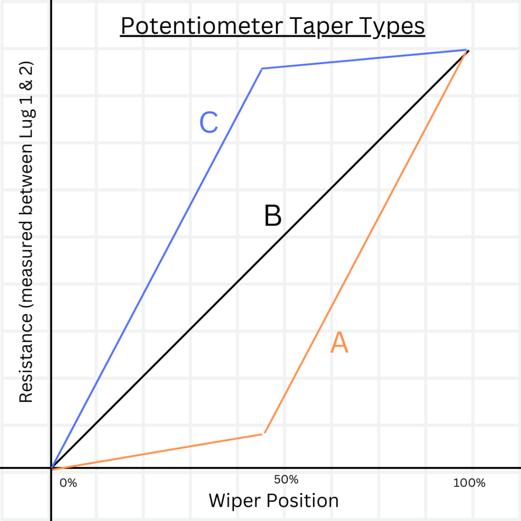
The linear taper pots are usually specified with the letter “B,” while the letter “A” signifies a logarithmic taper. Some refer to log pots as audio pots since they exhibit a linear change in decibels, which is a common unit of sound intensity/power level based on a logarithmic scale.
A Basic Potentiometer Circuit
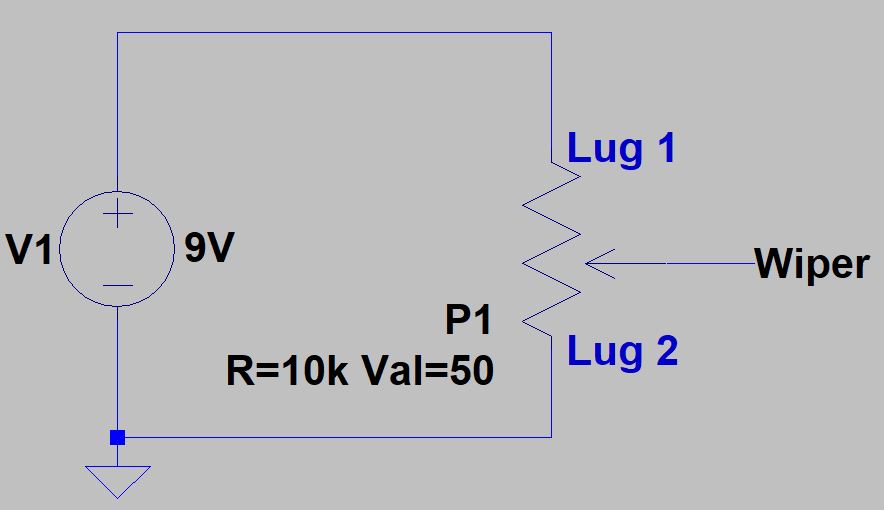
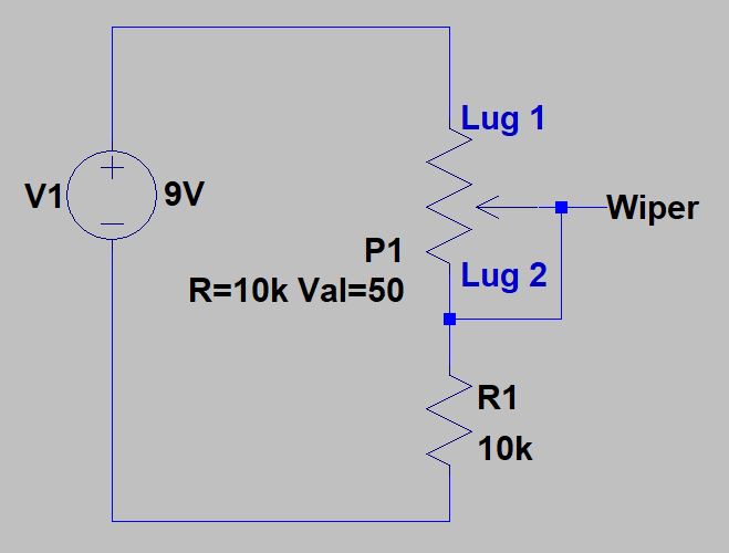
Figure 2 shows an example circuit depicting the operation of a potentiometer with DC voltage levels. If we turn the Wiper counter-clockwise to Lug 1 the voltage at the Wiper equals 9V. When the Wiper is rotated back to Lug 2 the voltage decreases to 0V.
Since this model exhibits a linear pot, when we rotate the Wiper to the half-way point the voltage at the output is 4.5V – half of the voltage present across Lug 1 and Lug 2.
The Three Potentiometer Configurations
Potentiometers are used for many different purposes, depending on the application. The way you wire them into your circuit usually follows one of three configurations:
- Open Configuration
- Variable Resistor Configuration
- Grounded-Lug Configuration
Open Configuration
The first configuration is the most basic configuration. None of the lugs of the potentiometer are connected to eachother and are, instead, open to being connected to other parts of the circuit.
For example, in Figure 2 above neither Lug 1 nor Lug 2 directly connect to the Wiper. In this case, the Wiper terminal would be used to provide a variable DC voltage, possibly for dialing in a bias voltage to be used elsewhere in the circuit.
Variable Resistor Configuration
The Variable Resistor configuration is encountered when one of the two outer lugs (Lug 1 or Lug 2) are tied to the Wiper. Take Figure 3 (below) as an example, where we have introduced a 10k resistor in series with a potentiometer resistance and have connected the wiper to Lug 2.
As the Wiper moves towards Lug 1 the voltage on the wiper gradually rises to 9V. When we turn the Wiper to Lug 2 the 10k resistor and the 10k potentiometer resistance form a voltage divider and 4.5V appears at the output.
In this example, the Wiper voltage is only able to sweep from 4.5V to 9V. Conversely, in the previous example (Figure 2) the range was 0V to 9V.
There are many reasons to use this configuration in your design. One common application involves the need for a variable resistance in the feedback path of a drive stage to increase or decrease the gain applied by an op amp (see the SD-1 Overdrive circuit’s gain stage).
Grounded-Lug Configuration
This third configuration can be thought of as a special-case of the Open Configuration. The only difference being that one of the outside lugs (Lug 1 or Lug 2) connects to ground.
Return your attention to Figure 2 as an example of a Grounded-Lug configuration. The most prevalent audio application for this configuration is a volume or level control (refer to the Tubescreamer circuit‘s level control).
Virtual Ground
There are two different contexts when speaking about ground:
- Power Ground
- Virtual Ground
Power ground is the reference point by which you measure the power supply voltage and other DC voltages. If the power supply voltage is 9V, then it is 9V with respect to power ground.
Virtual ground is the reference voltage level that the audio signal is biased to. In this case, a virtual ground of 4.5V means that the guitar signal varies around 4.5V. For an example of a grounded-lug configuration using the virtual ground, see the SD-1 circuit and its’ approach to level control.
The PROTIS 1 Potentiometer Interface
The Potentiometer Interface includes six (6) on-board potentiometers. The resistance values were carefully chosen to cover a large range of values. Not all resistance ranges can be covered, however, so two (2) External Pot connections are available on the far-left.
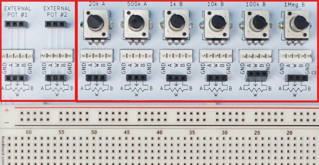
Each potentiometer is fitted with a 3-pin female socket header, allowing jumper wire access to the three terminals on the potentiometer.
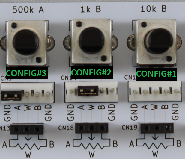
Additionally, each potentiometer is fitted with a 5-pin male header that introduces the ability to easily configure the potentiometer connections as per the explanations above. Simply use a jumper like the ones shown in Figure 5.
Meet the Author:

Hi, I’m Dominic. By day, I’m an engineer. By night, I repair and modify guitar effects! Since 2017, I’ve been independently modifying and repairing guitar effects and audio equipment under Mimmotronics Effects in Western New York. After coming out with a series of guitar effects development boards, I decided the next step is to support that community through content on what I’ve learned through the years. Writing about electronics gives me great joy, particularly because I love seeing what others do with the knowledge they gain about guitar effects and audio circuits. Feel free to reach out using the contact form!