[Last Updated: January 3, 2024]
As a member of the Reverb Partner Program and as an Amazon Associate, StompboxElectronics earns from, and is supported by, qualifying purchases.
Disclaimer: Stompbox Electronics and/or the author of this article is/are not responsible for any mishaps that occur as a result of applying this content.
What is True Bypass?
The idea behind True Bypass wiring is simple: when bypassing a guitar pedal the signal should be routed directly from the input jack to the output jack with minimal interference.
Nothing should get in the way of the guitar signal when the pedal is true-bypassed. The reason? To avoid tone suck and ensure that the signal going into the pedal is the same one coming out.
Testing a Guitar Pedal for True Bypass
A True Bypass pedal in bypass mode will allow your guitar signal to pass through it whether or not power is applied to the pedal.
It’s easy to test if your pedal is True Bypass, just follow these steps:
- Plug a guitar into the pedal’s input.
- Plug an amp into the pedal’s output.
- Ensure there is no power applied to the guitar pedal.
- While the pedal is in bypass mode, turn on the amplifier and try to play through the pedal.
If you hear your guitar signal while the pedal is in bypass mode, then you have a True Bypass pedal!
True Bypass Explained
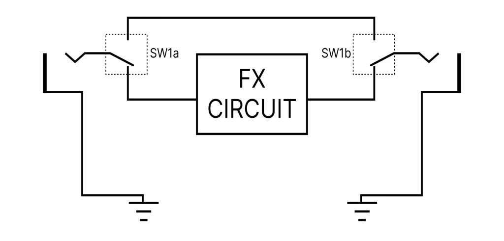
Figure 1.1 presents a clear idea of what we’re aiming for. The switch SW1 is called a double-pole double-throw switch (DPDT). The number of poles signify the number of ‘switches’. The number of throws signifies how many directions you’re able to set for each pole.

In this case, there are 2 poles: SW1a and SW1b. Each pole has two possible directions (“double”-throw). The first pole (SW1a) is used to route the input signal. The other pole (SW1b) is used to route the output signal.
Most times you’ll want an indicator light to let you know when the pedal is engaged or disengaged. In that case, you will need one more pole. Instead of a Double-Pole Double-Throw (DPDT), you will need a Triple-Pole Double-Throw (3PDT).
True Bypass Wiring
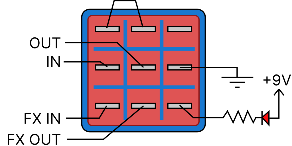
The wiring diagram in Figure 1.2 is one of the most common ways to wire a True Bypass switch. You can use this picture as a guide.

Regarding the block diagram in Figure 1.1, the first column represents SW1a while the second column represents SW1b. The third column is the additional pole used to switch ON and OFF an LED.
There are a total of two positions (“double-throw”) in this switch. In the first position the top two lugs of each column are connected, allowing you to bypass the main guitar effect circuit. In the second position the bottom two lugs of each column are connected, allowing you to route the signal to and from the effect pedal circuit.
Here’s a quick video describing the same 3PDT configuration:
True Bypass Parts List
You can implement the True Bypass circuit with 4 simple parts: a 3PDT switch, a 1kΩ resistor, a light-emitting diode (LED), and two guitar jacks
| Parts | Qty |
|---|---|
| 3PDT Footswitch | 1 |
| 1kΩ Resistor | 1 |
| Light-Emitting Diode (LED) | 1 |
| 1/4″ Input/Output Jack | 2 |
Where to Buy
Guitar pedal footswitches are easily found doing a quick internet search. There are large electronics distributors like Mouser, DigiKey, Arrow, and Newark that are readily accessible for basic electronic components.
For guitar pedal parts specifically, you’ll need to look at more niche distributors. LoveMySwitches, Small Bear Electronics, GuitarPedalParts, and DIYPedalGearParts are all good options.
True Bypass with the PROTIS 1
The PROTIS 1 Development Board has a True Bypass circuit embedded into it’s design. For this reason, when you design your effects on the PROTIS 1, there is no need to build the True Bypass circuit yourself when prototyping.
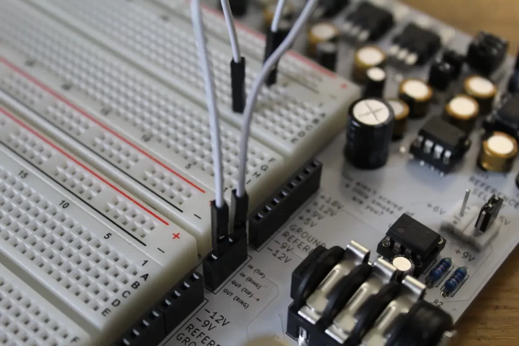
If you’re following along using the PROTIS 1, take a look at the input/output headers.
The input signal comes from a terminal marked IN (TIP). Likewise, the output signal goes to the OUT (TIP) terminal.

Plug your guitar into the input jack, located on the right side of the board. Plug your amp into the output jack, located on the left side of the board.
When you strum, you should hear your guitar signal playing through the amp. If you can’t hear it, then the board is not in “bypass” mode. Press on the 3PDT switch to toggle between Engaged Mode to Bypass Mode.
Other Bypass Circuits
The wiring scheme in Figure 1.2 isn’t the only way to bypass a guitar pedal. Other methods have been developed over the years, including the Millenium Bypass, CD4053 Bypass, and Relay Bypass.
Millenium Bypass
The 3PDT switch allows you to have True Bypass and an indicator light. However, 3PDT switches are more expensive than their DPDT counterparts, so it would be great to have a bypass circuit that gives us the benefits of True Bypass and an indicator LED using the less expensive DPDT switch.
In 1999 R.G. Keen noticed the DPDT switching method used in later RAT pedals could be improved. He figured out a way to add in an indicator LED while reducing the load on the output signal, all using the cheaper DPDT and a handful of parts. He called this method the Mellenium Bypass.
Relay True Bypass
Another way to construct a True Bypass circuit is by using a relay. A relay is a device that uses magnetism to perform switching.
It works like this: a coil of wire becomes energized by applying a voltage across it. The current flowing through that coil produces a magnetic field which closes a pair of metal contacts. If you remove the voltage, it halts the current flow through the coil and kills the magnetic field, which allows the contacts to open.
This method is more advanced, since it usually requires a microcontroller and a specially designed circuit for energizing and de-energizing the relay coil. Most microcontrollers cannot handle the standard 9Vdc voltage used in modern pedal designs. For this reason, a 5Vdc regulator is also often required to power the microcontroller circuit. Many modern pedals utilize this method, like the Line 6 DL-4 among others.
For DIY, if you do not have microcontroller experience you can still opt to purchase ready-to-use kits, complete with parts, a programmed chip, and a circuit board.
Additionally, if you’re a proud owner of a PROTIS 1 development board and interested in working with microcontroller circuits, check out the PROTIS 1 PIC Development Board Module.
CD4053 Bypass
In another 2000 GeoFex article, R.G. Keen described another electronic bypass method using two integrated circuits (ICs): the CD4053 and CD4013. This method is utilized in most Behringer pedals and is not considered True Bypass, because the ICs require power to carry the signal.
The CD4053 3PDT Analog Switch is basically an electronic equivalent to the mechanical 3PDT switch described above. The CD4053 chip requires an ON/OFF electrical signal to bypass/engage the switching mechanism.
The CD4013 Dual D Flip-Flop IC is often used to provide the “toggle” signal to the CD4053. To trigger the toggle action, you can use a simple momentary switch connected to the CD4013.
BOSS-Style JFET Bypass
BOSS and Ibanez pedals employ JFETs (Junction Field-Effect Transistors) to handle bypassing. This is not a True Bypass method, but it is popular and worth reading up on if you are interested in modifying BOSS pedals. Read more about the BOSS/Ibanez style bypass switching here.
Guitar Effects Design in 48 Circuits or Less
The 48 Circuits or Less article series serves to close the gap between DIY guitar effects design and guitarists interested in the craft by uniquely curating the most important aspects of DIY guitar effect circuit design. This post is part of the 48 Circuits or Less series. View more articles in this series here.
Meet the Author:

Hi, I’m Dominic. By day, I’m an engineer. By night, I repair and modify guitar effects! Since 2017, I’ve been independently modifying and repairing guitar effects and audio equipment under Mimmotronics Effects in Western New York. After coming out with a series of guitar effects development boards, I decided the next step is to support that community through content on what I’ve learned through the years. Writing about electronics gives me great joy, particularly because I love seeing what others do with the knowledge they gain about guitar effects and audio circuits. Feel free to reach out using the contact form!
The Tools I Use
As a member of Amazon Associates, Stompbox Electronics earns and is supported by qualifying purchases.


