
This post surrounds the repair of a T-Rex Engineering Hobo Drive afflicted with the dreaded “no signal” symptom. I cover the features of the Hobo Drive and some details about its’ circuit.

As a member of the Reverb Partner Program, eBay Partner Network, and as an Amazon Associate, StompboxElectronics earns from, and is supported by, qualifying purchases.
Disclaimer: Stompbox Electronics and/or the author of this article is/are not responsible for any mishaps that occur as a result of applying this content.
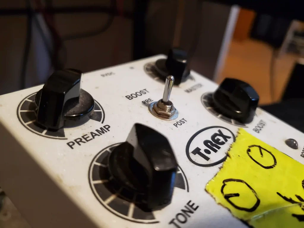
The T-Rex Engineering Hobo Drive
The T-Rex Engineering Hobo Drive is a dual overdrive/booster pedal that features a tight, grainy low-medium overdrive coupled with a clean and independent booster. Both circuits can be used independently or stacked in any order.
The main features of the Hobo Drive include:
- 2-stage preamp, with PREAMP and MASTER volume controls
- 2-way selector switch for PRE-Boost or POST-Boost
- TONE control
- BOOST control + BOOST footswitch
- True Bypass Switching
- 9VDC Operation
The Hobo Drive Circuit
The Hobo Drive is the definition of an op amp overdrive. It’s circuit surrounds a handful of TL072 op amps in SMD packages. Switching is accomplished using CD4013 D-Flip Flop in conjunction with MMBFJ113 N-Channel JFETs.
There are five main circuit blocks in the Hobo Drive, and their order is dependent on how you set the PRE/POST toggle switch. If you set the toggle to PRE, the signal gets boosted before entering the drive circuit. If the toggle is set to POST, the signal is boosted after the drive circuit.
Let’s say the toggle is set to PRE. The five main circuit blocks, in the order that the signal encounters them, are:
- Non-Inverting Amplifier (Boost Circuit)
- Op-Amp Buffer #1
- Non-Inverting Amplifier with Active Filtering & Hard Clipping (Drive Circuit)
- Single-Pole Non-Inverting Active Filter (Tone Circuit)
- Op-Amp Buffer #2
Hobo Drive Repair
Troubleshooting & Diagnosis
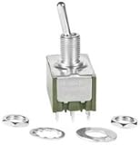
The Hobo Drive was given to me because no signal was passing through it. I immediately found that the PRE/POST toggle switch had locked up in a single direction. After getting my hands on a schematic from a Freestompboxes post, I confirmed the operation of that switch was to route signal flow. That made me zone in on replacing the toggle switch.
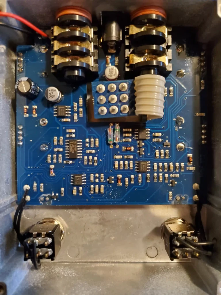
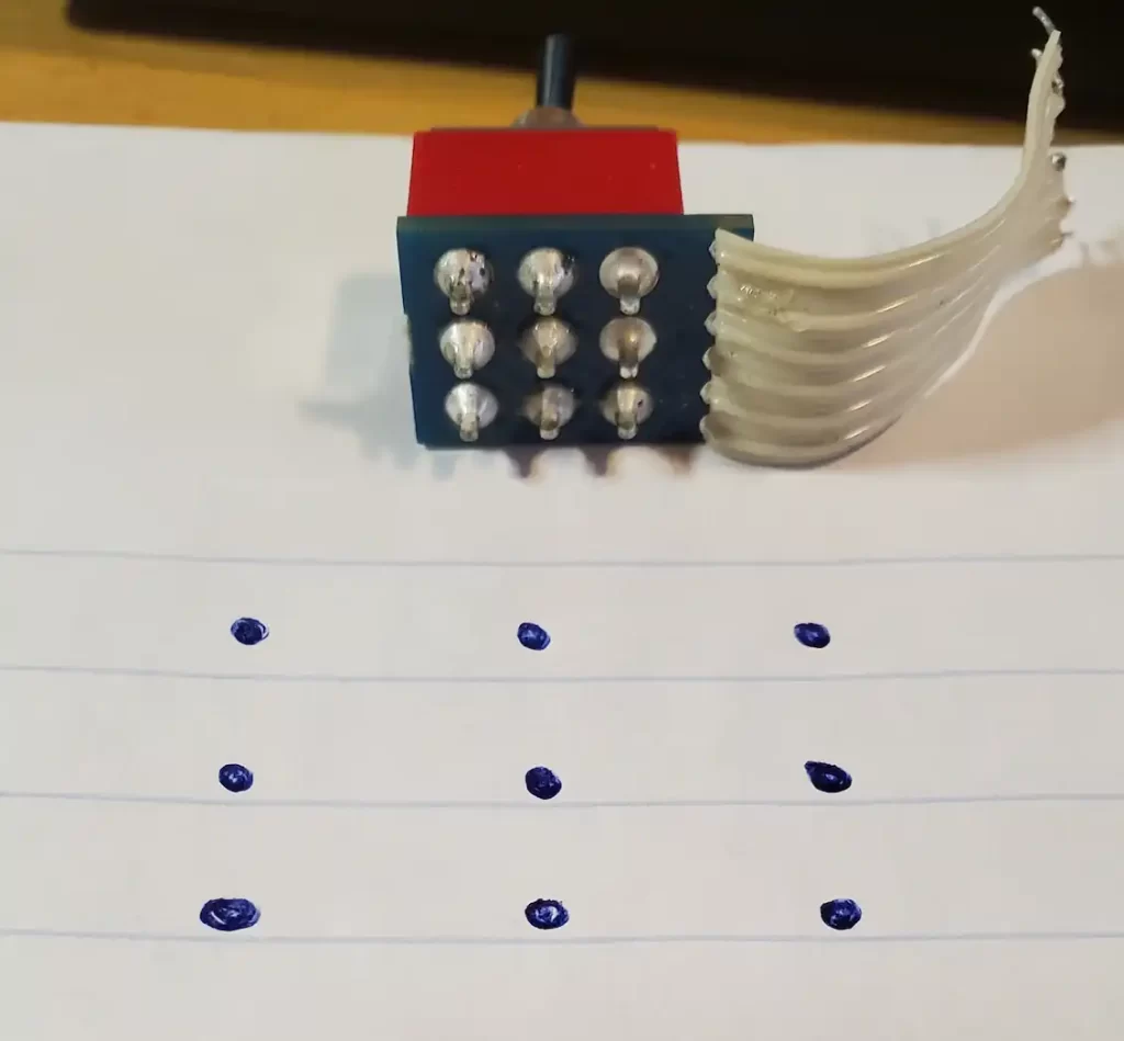
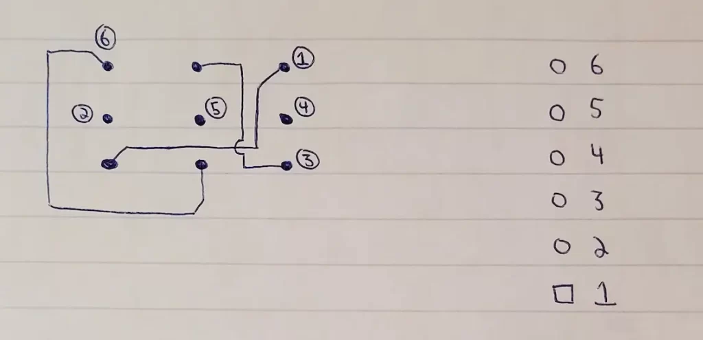
The 3PDT toggle switch is mounted on it’s own daughter-board and connected to the main board via ribbon cable. Unfortunately the schematic did not include the wiring for the toggle switch, so I reverse engineered it on a piece of paper (see below).
Repairing the Hobo Drive
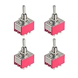
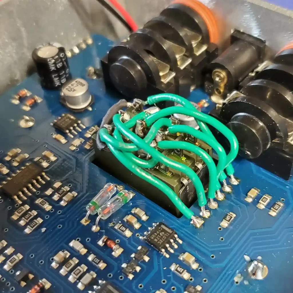
Firstly, we need to remove the toggle switch (shown below). I didn’t have a 3PDT toggle switch on-hand, but I did have a 4PDT toggle from a Small Stone Univibe Mod I had tried a while back. So instead of waiting for a replacement part, I used 3 of the 4 poles on the 4PDT toggle.
The part number for the 4PDT is M2042SS1W01 from NKK Switches. Amazon has a 3PDT solder-lug toggle switch, which is a more direct replacement in this case.
After removing the toggle switch, I traced out which pin connected to which wire in the ribbon cable. The images below show the wiring for the toggle switch. In the end, I used these diagrams to solder in the replacement toggle switch.
Meet the Author:

Hi, I’m Dominic. By day, I’m an engineer. By night, I repair and modify guitar effects! Since 2017, I’ve been independently modifying and repairing guitar effects and audio equipment under Mimmotronics Effects in Western New York. After coming out with a series of guitar effects development boards, I decided the next step is to support that community through content on what I’ve learned through the years. Writing about electronics gives me great joy, particularly because I love seeing what others do with the knowledge they gain about guitar effects and audio circuits. Feel free to reach out using the contact form!
The Tools I Use
As a member of Amazon Associates, Stompbox Electronics earns and is supported by qualifying purchases.


