
The EHX Small Clone uses a relaxation oscillator-based circuit for its LFO. These are fairly simple circuits that can be modified to include an LED to see the speed of the LFO. The mod involves drilling a hole into the existing enclosure and installing the new LED, along with some wiring changes.

As a member of the Reverb Partner Program, eBay Partner Network, and as an Amazon Associate, StompboxElectronics earns from, and is supported by, qualifying purchases.
Disclaimer: Stompbox Electronics and/or the author of this article is/are not responsible for any mishaps that occur as a result of applying this content.
Mod Overview
This modification involves using an emitter-follower, a couple resistors, and an LED to create a visual indicator showing the rate of the Small Clone’s LFO circuit.
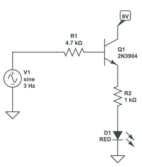
A circuit for LFO rate indication is shown using a 2N3904 BJT NPN transistor. The input to the circuit is fed from pin 1 of the LM358 op amp used to produce the LFO signal in the Small Clone.
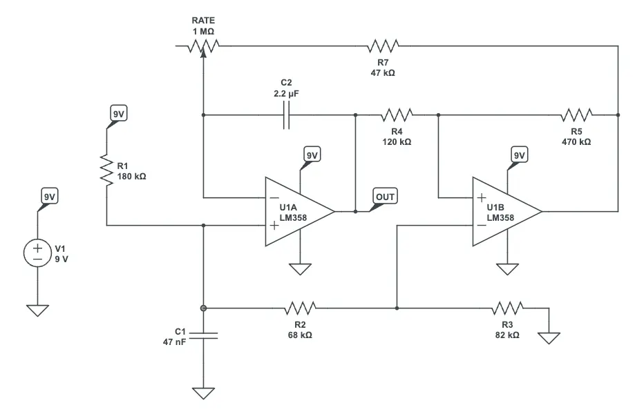
The Small Clone LFO Circuit
The EHX Small Clone uses a type of relaxation oscillator to generate its LFO signal. I simulated the circuit in CircuitLab to show you how it works, you can access that circuit by clicking on the image below.
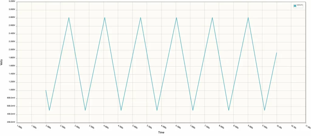
The output of the LFO circuit is taken from the output pin of U1A, which happens to be pin 1 of the LM358. The type of signal is a triangle wave at maximum depth (see below). You can control the rate using the 1 Mega-Ohm Rate potentiometer.
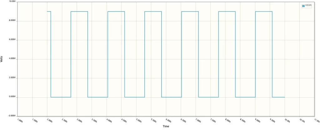
As an aside, these style LFOs also produce a square wave. In this case, it can be found at pin 7 of the LM358, which is the output of U1B in the schematic above. This provides a modification opportunity for toggling between triangle and square waves. One thing to notice, though, is the amplitude of the square wave is much higher than the triangle wave so there may be some attenuation required.
A Circuit for LFO Rate Indication
One common approach to building an LFO rate indicator circuit involves using an emitter-follower topology. In this way, the LFO circuit won’t be too loaded.
As you saw above, the triangle wave signal rises up to about 2.8V and falls to around 500mV. An attenuated version of that signal appears at the base terminal of the 2N3904. Subtracting the 0.65V standard voltage drop across the transistor’s base and emitter terminals, the voltage range across the LED circuit will be 0 to 2.15V, as shown with the blue voltage signal below.
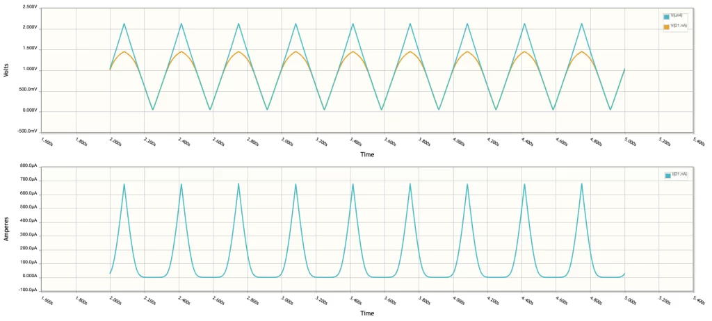
The yellow voltage signal represents the voltage across the LED. When the voltage crosses above the standard forward voltage drop of the LED it starts to conduct current. The blue line on the bottom shows those spikes in current in tempo with the LFO rate. When the LED conducts current it lights up, giving you a visual indication of the LFO frequency.
Meet the Author:

Hi, I’m Dominic. By day, I’m an engineer. By night, I repair and modify guitar effects! Since 2017, I’ve been independently modifying and repairing guitar effects and audio equipment under Mimmotronics Effects in Western New York. After coming out with a series of guitar effects development boards, I decided the next step is to support that community through content on what I’ve learned through the years. Writing about electronics gives me great joy, particularly because I love seeing what others do with the knowledge they gain about guitar effects and audio circuits. Feel free to reach out using the contact form!
The Tools I Use
As a member of Amazon Associates, Stompbox Electronics earns and is supported by qualifying purchases.


