
I received this MXR Analog Chorus on a trade, from which I received 3 other non-working pedals – a Vox V847 Wah Wah, an MXR Carbon Copy, and a Line 6 Constrictor. After plugging in the Analog Chorus I realized it was completely dead – zero output. The LED didn’t even light up when stomping in and out of effect mode.
Right away, I’m thinking there’s something wrong with either the bypass switch or the power circuit. Let’s take a look…

As a member of the Reverb Partner Program, eBay Partner Network, and as an Amazon Associate, StompboxElectronics earns from, and is supported by, qualifying purchases.
Disclaimer: Stompbox Electronics and/or the author of this article is/are not responsible for any mishaps that occur as a result of applying this content.
Troubleshooting the MXR Analog Chorus
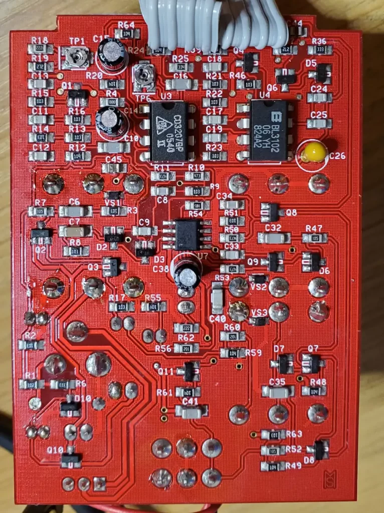
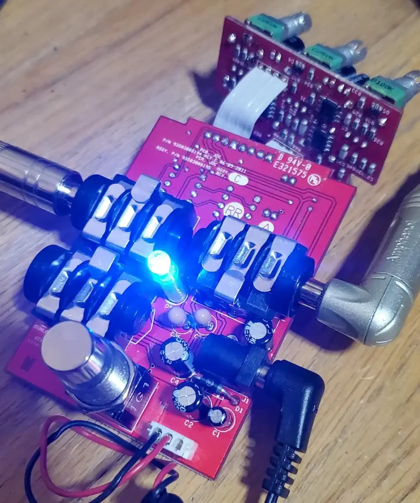
Removing the four screws on the back plate of the pedal reveals the circuit board. I don’t see anything immediately wrong – no cold solder joints or bulging capacitors.
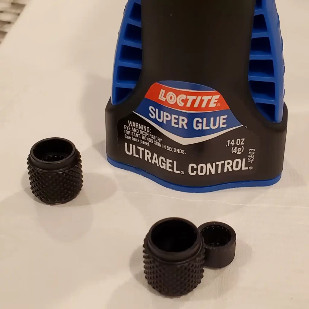
I decided to fully disassemble the pedal by removing the jacks on the side and the 5 knobs on top. Two of the knobs were a little loose when removing them, so I added some glue to hold them together (thank you, Loctite Super Glue).
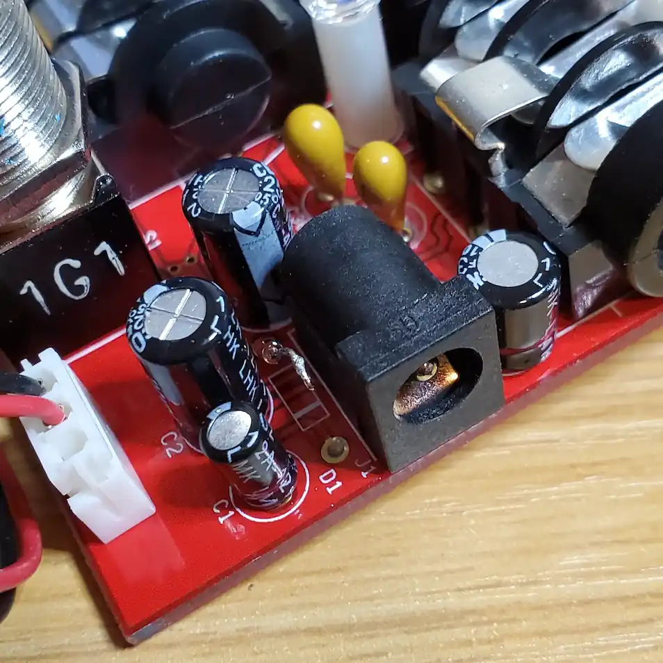
After removing the board, I plugged in the power and started probing voltages. The measurements across the power connector were showing extremely low voltage (almost zero). There should have been 9V at the power connector…it sure seems like something is shorting the power rails.

There was a series protection diode situated directly next to the power connector. Knowing that these are designed to short out when a reverse polarity is applied to the pedal, I decided to lift one of its’ leads and apply 9V power again. This time I was able to measure 9V at the power connector and all the IC chips, so I was pretty confident that replacing that series diode would fix the issue.
Repairing the MXR Analog Chorus
Usually protection diodes are 1N400x style, but this looked more like the 1N4148’s I usually see and use for clipping circuits. In any case, I removed the stock series protection diode and replaced it with a 1N4001 rectification diode.
After replacing the series protection diode, the MXR Analog Chorus was back in action!
Troubleshooting Other Issues with the MXR Analog Chorus
In my case, the original symptom was that the pedal didn’t power on at all. In general, if this happens you should always measure the voltage at the power connector. That measurement will rule out any problems with the protection diode.
Other potential symptoms might include:
- The pedal powers on, but there’s no effect.
- The pedal powers on, but there’s no output at all.
Pedal Powers On, No Effect
If the dry signal comes through but there’s no effect, then there’s either a problem with the LFO generator, an issue with the delay signal reaching the output mixer, or a failure of the BBD circuit itself.
The LFO generator is located on the same circuit board that the pots are mounted. The TL062 is likely configured as a relaxation oscillator with the LFO signal routed through one of the ribbon cables to the main board.
Testing the continuity of the ribbon cables and reflowing the soldered wire connections would be my first attempt. Then, I would check the voltage measurements of the TL062 op amp.
To test whether the delay signal is reaching the output mixer, you need to get your hands on an audio probe. Follow the signal from the output pin of the 3207 BBD chip (pins 7 and 8). Trace the audio path with the audio probe until you hear something that doesn’t sound right (or until the audio totally drops off). The problem is probably around that area.
Testing whether the BBD chip is actually working will also require an audio probe. Test to make sure there is audio at the input pin of the BBD (pin 3). If the input is present, and there’s no output signal coming from the BBD chip, then there’s a problem in the BBD circuit. It could be biasing issues (pin 4, Vgg), a failure of the clock generator, or a failure of the BBD chip itself. These are best troubleshot using an oscilloscope.
Pedal Powers On, No Output At All
If there’s no wet or dry signal coming from your Analog Chorus, then the first check I would conduct would be the voltage check. Measure the voltages on all op amps. If all the pins on any of the op amps are at 9V while the ground pin is at zero, then the op amp might be bad and needs to be replaced.
If the voltages seem okay on the op amps, then the next step would be to audio probe the input signal and see where that takes me.
Meet the Author:

Hi, I’m Dominic. By day, I’m an engineer. By night, I repair and modify guitar effects! Since 2017, I’ve been independently modifying and repairing guitar effects and audio equipment under Mimmotronics Effects in Western New York. After coming out with a series of guitar effects development boards, I decided the next step is to support that community through content on what I’ve learned through the years. Writing about electronics gives me great joy, particularly because I love seeing what others do with the knowledge they gain about guitar effects and audio circuits. Feel free to reach out using the contact form!
The Tools I Use
As a member of Amazon Associates, Stompbox Electronics earns and is supported by qualifying purchases.


