
The Danelectro Dan-Echo LFO Modification initiated as an idea based on existing techniques for adding modulation to a PT2399 circuit. The Dan-Echo uses a PT2395, so the LFO Mod is an altered version of those techniques for the Dan-Echo.
This post walks you through the steps to modify your Dan-Echo with the LFO Modification.

As a member of the Reverb Partner Program, eBay Partner Network, and as an Amazon Associate, StompboxElectronics earns from, and is supported by, qualifying purchases.
Disclaimer: Stompbox Electronics and/or the author of this article is/are not responsible for any mishaps that occur as a result of applying this content.
The schematics shown here are excerpts from the original tracer, Mr. Basoni from March 28th, 2013.
About the Dan-Echo LFO Mod
The Danelectro Dan-Echo LFO Modification initiated as an idea based on existing techniques for adding modulation to a PT2399 circuit. The Dan-Echo uses a PT2395, so the LFO Mod is an altered version of those techniques for the Dan-Echo.
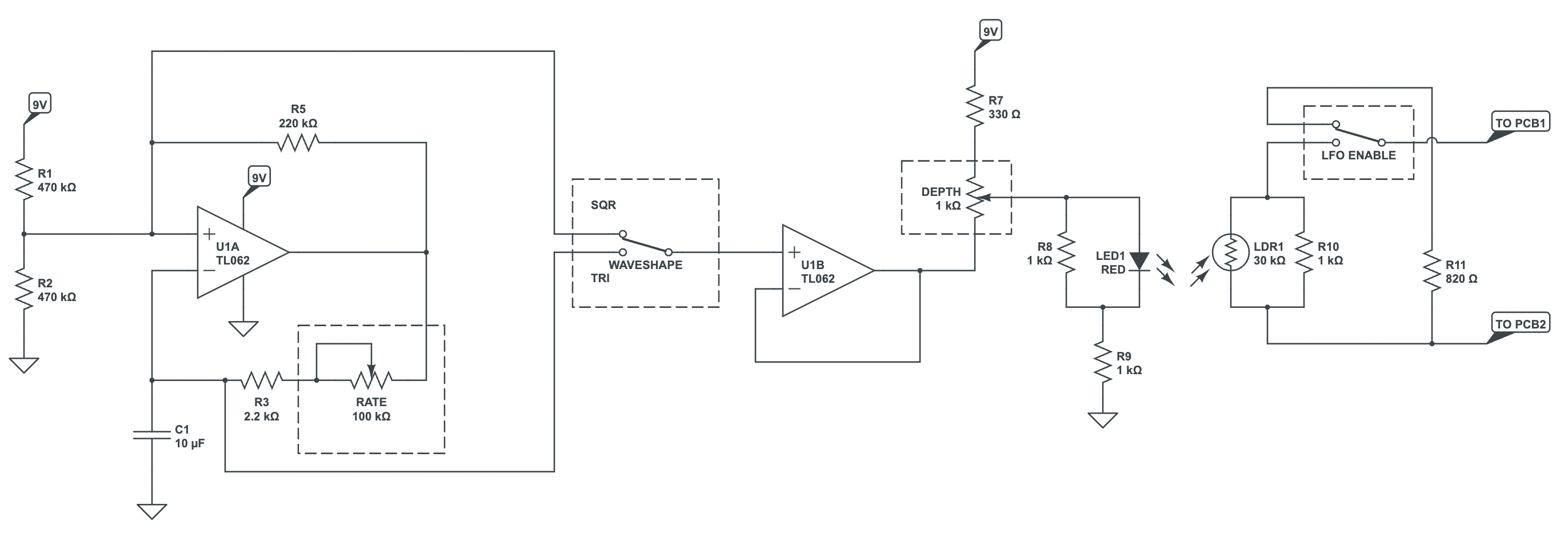
The low-frequency oscillator (LFO) is built using a dual low-power operational amplifier. A TL062 op amp is recommended, since it is the low-power version in the TL0x2 family.
Find a TL062 on:
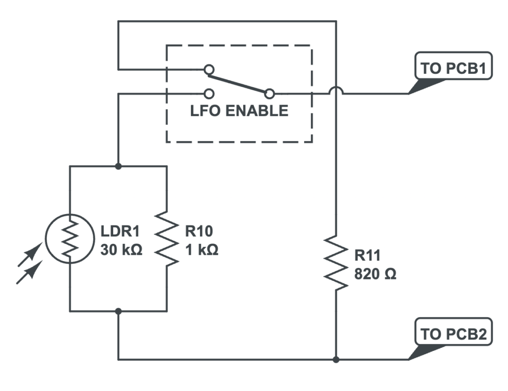
There are a few ways to build LFOs. This mod utilizes a relaxation oscillator (as shown in the schematic below). This relaxation oscillator calculator can help you design one of your own, if you wish.
The second op amp in the dual package is used to buffer the LFO signal. Switching between square and triangle waves can be done using a simple toggle switch. Similarly, the LFO mod is enabled using an “LFO Enable” toggle switch. The LFO Enable switch toggles between the LDR’s resistance and a stock resistance value of 820 ohms.
Compatible Versions
This modification is compatible with both the through-hole and surface-mount version of the Dan-Echo.
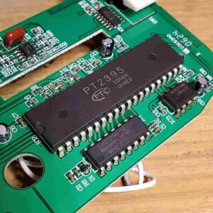
There is at least one surface-mount version of the Dan-Echo that does not utilize the PT2395. That version is not compatible with the LFO Mod, so please check whether your Dan-Echo circuit has the PT2395 echo chip before starting.
Required Tools for the LFO Mod
Standard tools typical of guitar pedal modifications are required to carry out the LFO Modification. These instructions assume you have the knowledge to operate the tools and carry out the modification without doing harm to your Dan-Echo.
See the table below for a list of recommended tools for the LFO Mod:
| Tool | Recommendation | Where to Find |
|---|---|---|
| Soldering Station/Iron | Weller Digital Soldering Station – WE1010NA | Amazon | eBay |
| Solder | Kester Solder 24-6040-0027 | Amazon | eBay |
| Wire Strippers | Klein Tools 11063W Wire Cutter / Wire Stripper, Heavy Duty Automatic Wire Stripper Tool | Amazon | eBay |
| Precision Tweezers | 6PCS Precision Tweezers Set | Amazon | eBay |
| Drill Press | 10 in. Bench Mount Drill Press, 12 Speed by Central Machinery | Amazon | eBay |
| Drill Bit Set | DEWALT Titanium Nitride Coated Drill Bit Set with Pilot Point | Amazon | eBay |
| Automatic Center Punch | Automatic Center Punch, Pamiso 5.1 Inch Spring Loaded Drill Punch Tool | Amazon | eBay |
| Deburring Tool | General Tools 196 Short Length Hand Reamer & Countersink, 3/4″ | Amazon | eBay |
Surface-mount Version
For the surface-mount version, the best tool to have is a hot-air desoldering station. A hot air station helps you desolder surface-mount components.

Required Parts for the LFO Mod
Whether you’re applying the modification to the through-hole or the surface-mount version, the parts are the same for both.
If you would like to purchase a general parts kit instead of purchasing each part individually, here are some recommended resistor and capacitor kits that have all the values required for this mod:
- 1500 Pcs 75 Values (Each Values 20pcs) Resistor Kit 1 Ohm-10M Ohm Commonly Used 5% 100r Four Color Ring 1/4W Metal Carbon Film Resistors Classification
- BOJACK 24Value 630pcs Aluminum Electrolytic Capacitor Assortment Box Kit Range 0.1uF-1000uF
Parts List
Below is a list of the required parts for the LFO Mod:
| Part | Qty | Description | Where to Find |
|---|---|---|---|
| Light-Dependent Resistor (LDR) | 1 | PHOTO CONDUCTIVE CELL RESISTOR LDR 540NM RADIAL 5528 | Tayda |
| 5mm Red LED | 1 | LED 5MM RED SUPER BRIGHT | Tayda |
| TL062 Dual Low-Power Operational Amplifier | 1 | TL062 DUAL LOW-POWER JFET-INPUT OP-AMP IC | Tayda | Amazon | eBay |
| 330 Ω Resistor | 1 | 330 OHM 1/8W 1% METAL FILM RESISTOR ROYAL OHM TOP QUALITY | Tayda |
| 820 Ω Resistor | 1 | 820 OHM 1/8W 1% METAL FILM RESISTOR | Tayda |
| 1kΩ Resistor | 3 | 1K OHM 1/8W 1% METAL FILM RESISTOR ROYAL OHM TOP QUALITY | Tayda |
| 2.2kΩ Resistor | 1 | 2.2K OHM 1/8W 1% METAL FILM RESISTOR ROYAL OHM TOP QUALITY | Tayda |
| 220kΩ Resistor | 1 | 220K OHM 1/8W 1% METAL FILM RESISTOR ROYAL OHM TOP QUALITY | Tayda |
| 470kΩ Resistor | 2 | 470K OHM 1/8W 1% METAL FILM RESISTOR ROYAL OHM TOP QUALITY | Tayda |
| 1kΩ Linear “B” Potentiometer | 1 | 16mm Potentiometers – 18T Knurled Shaft – Solder Lug | LoveMySwitches |
| 100kΩ Linear “B” Potentiometer | 1 | 9mm Potentiometers – 18T Knurled Shaft – Vertical PCB Mount | LoveMySwitches |
| ON-ON Toggle Switch | 2 | Taiway SPDT On On Switch – Solder Lug – Short Shaft | LoveMySwitches |
| 10µF Electrolytic Capacitor | 1 | 10UF 25V 105C RADIAL ELECTROLYTIC CAPACITOR 5X11MM | Tayda |
| Heatshrink | – | Heat Shrink Tubing Kit | Amazon | eBay |
| Knobs, Knurled Shaft | 2 | Sandblasted Aluminum Knob – “The Pantherkill” – 18T Knurled Shaft (10mm OD) | LoveMySwitches |
| DIY Prototyping Board | 1 | HiLetgo 20pcs 5x7cm Bakelite DIY Prototype Board PCB 5 * 7cm | Amazon |
Dan-Echo LFO Mod Instructions
For both versions, the LFO Mod is generally the same – only the last few steps change.
Please note that the LFO Mod takes away the ability to operate the Dan-Echo with a battery. The battery compartment is needed to fit the LFO Mod board and panel-mount components.
Here are the steps that are independent of both versions:
- Build the LFO Circuit
- Build the LDR Circuit
- Connect the Rate Control to the LFO Circuit
- Connect the Depth Control to the LFO and LDR Circuits
- Connect the Wave Shape Toggle Switch to the LFO Circuit
- Connect the LFO Enable Toggle Switch to the LDR Circuit
- Open the Pedal and Remove the Circuit Board
- Drill the Mounting Holes for the Pots & Toggles
For the Through-Hole version:
- Connect the Power Wiring
- Remove resistor R4 (820 Ω)
- Connect the LDR Circuit to the DE-1 Board
- Mount the Controls
For the Surface-Mount version:
- Connect the Power Wiring
- Remove resistor R4 (820 Ω)
- Connect the LDR Circuit to the DE-1 Board
- Mount the Controls
Instructions for Both Versions
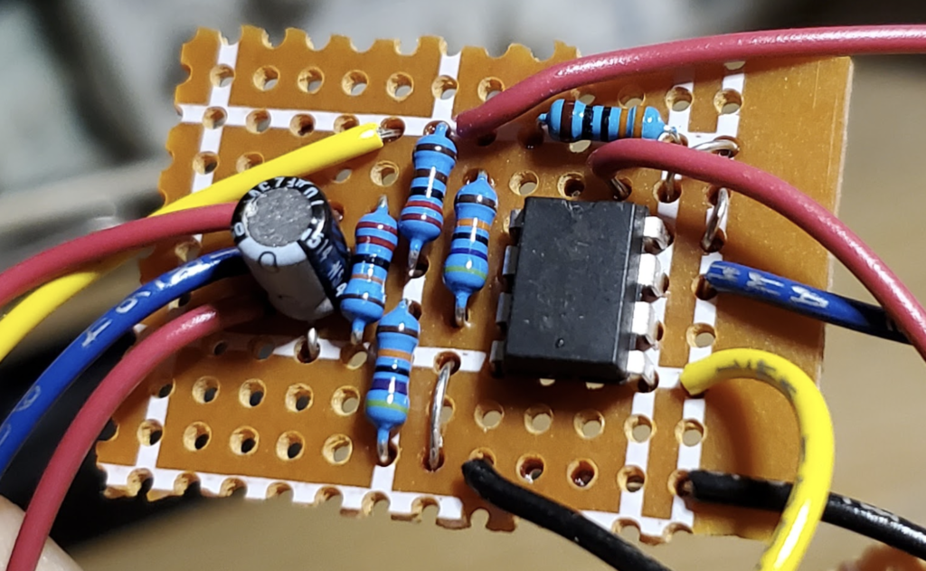
1. Build the LFO Circuit
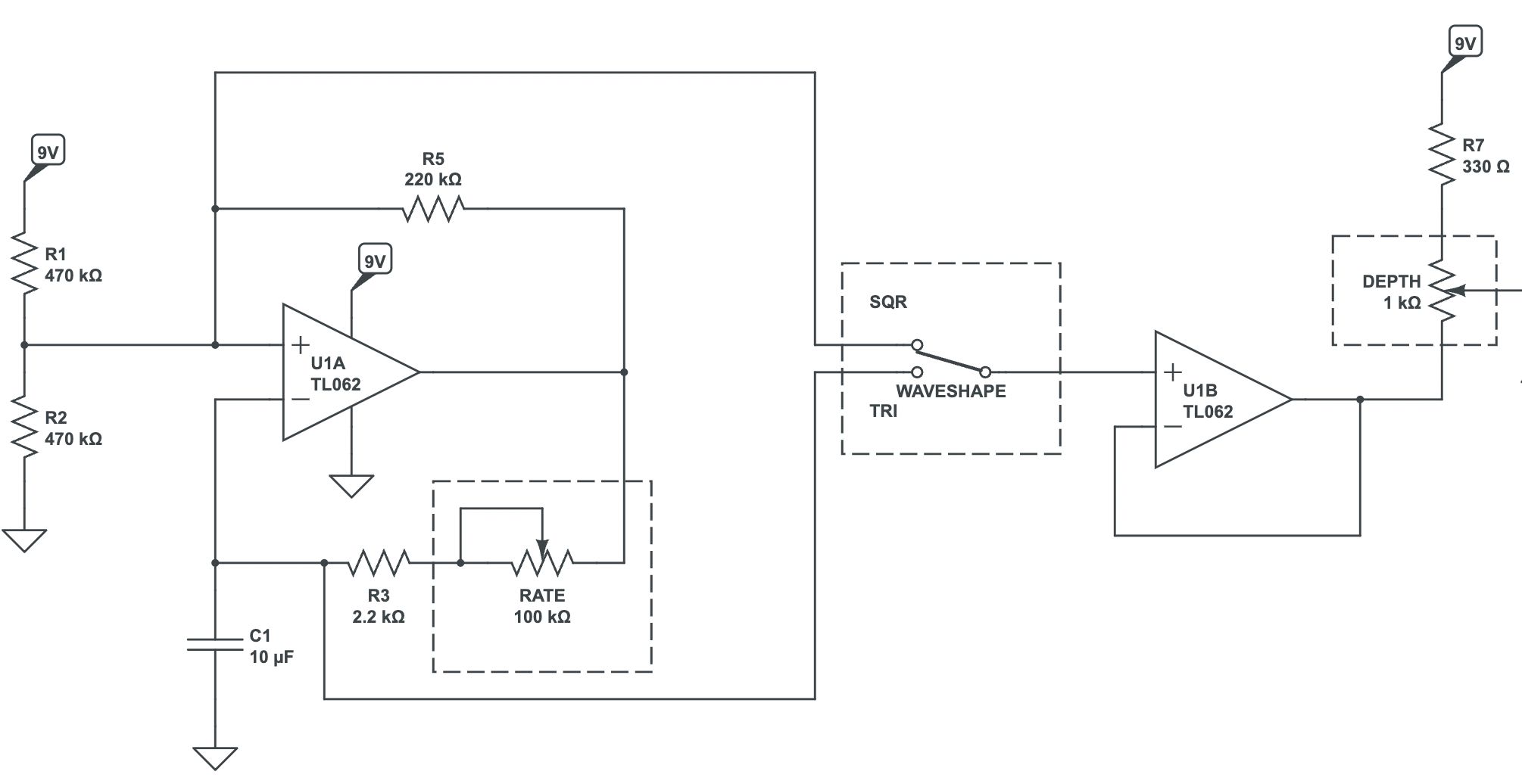
First, let’s build the low-frequency oscillator circuit on prototyping board. Follow the schematics below.
For the full LFO Mod schematic, see the About the Dan-Echo LFO Mod.
Be sure to make rails for the 9Vdc and ground rails. Also, make sure to leave spaces for the control components (Depth, Rate and Waveshape).
The U1A pinout on the TL062 is:
- Output: pin 1
- Inverting (-): pin 2
- Non-inverting (+): pin 3
The U1B pinout on the TL062 is:
- Non-inverting (+): pin 5
- Inverting (-): pin 6
- Output: pin 7
And the TL062 power pins are:
- Vcc: pin 8
- GND: pin 4


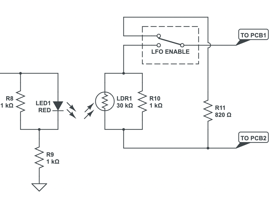
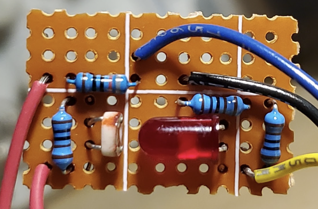
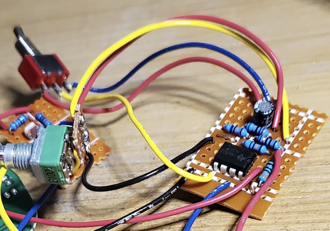
2. Build the LDR Circuit
Next step is to do the same as the first, but with the LDR Circuit. Refer to the schematic below for the LDR Circuit.
Please be sure there are spots open for the Depth Control connection (to the left, off-screen), the ground connection, the LFO Enable switch, and the “TO PCB2” wire.
The bottom of the board will be insulated with electrical tape. I usually wrap it all the way around the board and over the components. As a result the tape covers the LED and LDR, effectively containing the light from the LED.
You can also choose to face them towards each other inside a piece of heatshrink for a more direct effect.
3. Connect the Rate Control to the LFO Circuit
The Rate Control is wired as a variable resistor, ranging from 0 to 100kΩ. Lugs 1 and 2 are connected together and are wired to one end of the 2.2kΩ resistor (R3 in the Mod schematic below).
Lug 3 is connected to the Output pin (pin 1) of the op amp U1A.
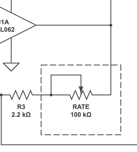
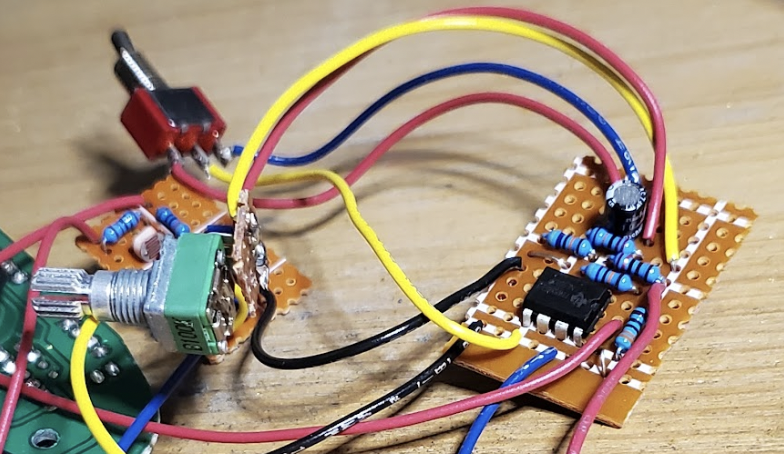
The recommended potentiometer for the Rate Control is the 9mm type. These are usually fitted with through-hole pins instead of solder lugs. In this case, I use a piece of prototyping board and land the hook-up wires at the prototyping board.
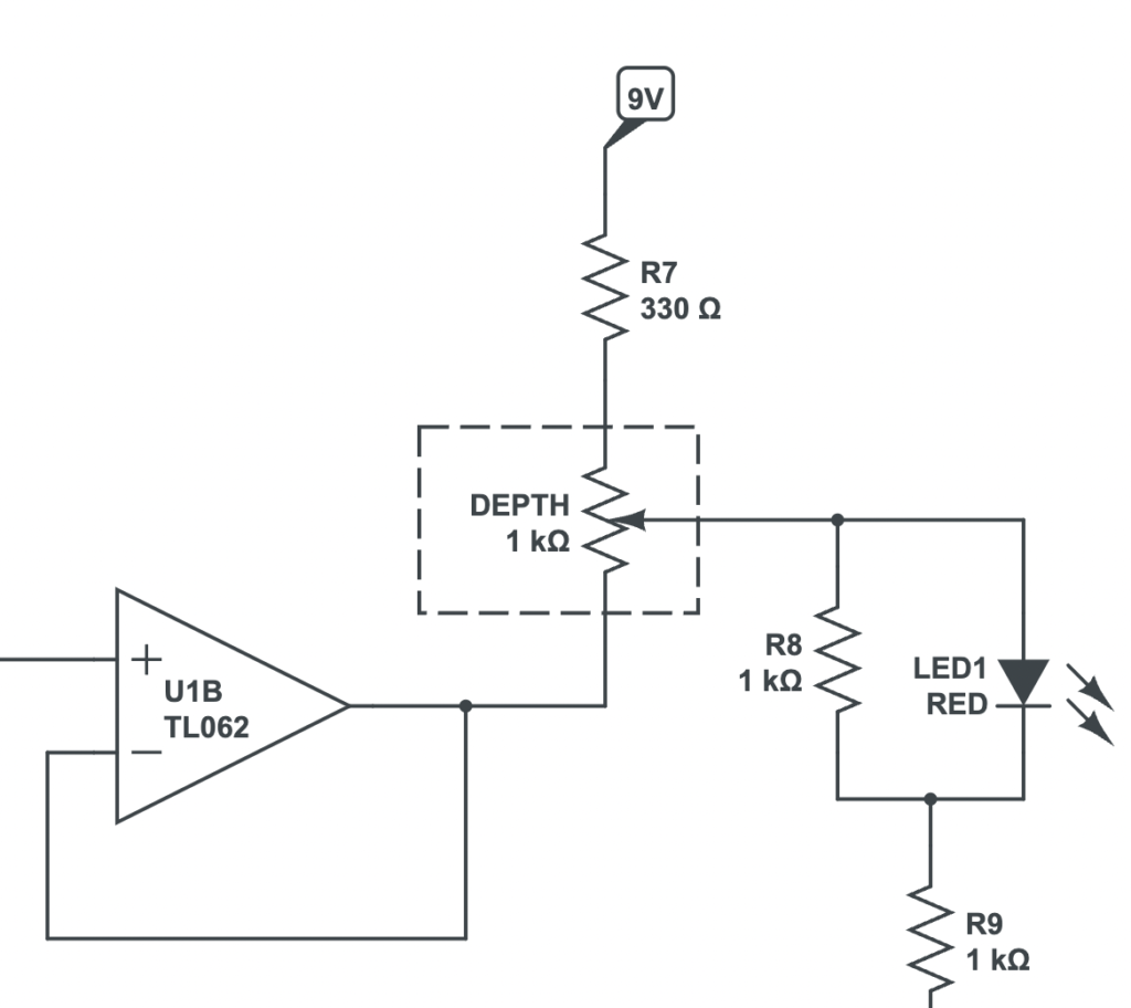
4. Connect the Depth Control to the LFO and LDR Circuits
Next up: the Depth Control. This potentiometer is wired to both the LFO and LDR boards.
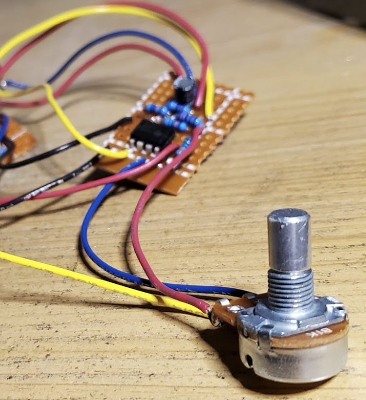
For this pot you can use the 16mm 1kΩ potentiometer, which will fit in the space between the battery compartment and the metal barrier running through the inside center of the pedal.
Wire the center lug to the anode of the LED on the LDR Circuit board. The maximum clockwise direction (lug 3) gets wired to the 330 Ω resistor on the LFO board. The maximum counter-clockwise position (lug 1) wires to the output of U1B (pin 7).
5. Connect the Wave Shape Toggle Switch to the LFO Circuit
Now we can wire the Wave Shape toggle switch. This switch is responsible for tapping into the square wave and triangle waves of the relaxation oscillator.
Use the excerpt below as a guide for wiring the Waveshape Toggle.
The square wave is accessed via the non-inverting input of U1A (pin 3). The triangle wave comes from the inverting input of U1A (pin 2).
Connect the common lug of the switch to the non-inverting input of U1B (pin 5).

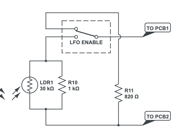
6. Connect the LFO Enable Toggle Switch to the LDR Circuit
Onto the next toggle switch: the LFO Enable. This switch is responsible for switching between the stock mode and the LFO Mod.
Use the schematic excerpt below as a guide for wiring the LFO enable switch.
The lug associated with “stock” behavior should connect to one side of the 820 Ω resistor. As for the direction associated with the LFO Mod, the lug should be wired to the LDR and 1k Ω, as shown.
As for the center/common lug, don’t worry about that just yet. Though, you can prep the wire and solder it onto the toggle switch in anticipation for when we connect it to the main board.
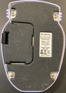
7. Open the Pedal and Remove the Circuit Board
Four screws hold in the bottom plate. Remove those along with the battery compartment.
The knobs on the top help to hold in the cream-colored plastic piece. Carefully pull off each of the four knobs and set them aside.
Next, there are two screws that hold in the daughter board (the one with the guitar and power jacks).
Under the daughter board is the main circuit board. There are either 4 or 6 metal screws (depending on your version) holding down the main circuit board that can be easily removed with a screwdriver.
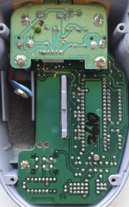
Once all the screws and the four knobs are removed you should be able to easily pull out the main board.
8. Drill the Mounting Holes for the Pots & Toggles
Now its time to drill the mounting holes for the potentiometer and toggle switch controls.
The first thing you’ll want to do is clear out the foam cushion used for the battery compartment.
Next, refer to the diagram below for component placement. The yellow circle denotes placement for the 9mm potentiometer, the cyan circle is for the 16mm potentiometer, and the red circles are for the toggle switches.
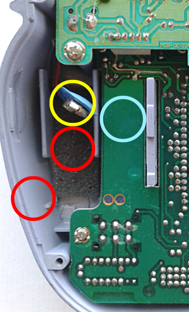
Be careful with the 16mm potentiometer placement. Be sure to avoid drilling into an uneven area on the topside of the pedal.
I use the red circle in the lower left for the LFO Enable switch. That hole is made into the side of the enclosure, so be careful about it’s placement in relation to the other toggle switch and circuit board.
Instructions for Through-Hole Version
This section covers the rest of the steps related to the through-hole version of the Dan-Echo. If you are modifying the surface-mount version, jump to the Instructions for the Surface-Mount Version.
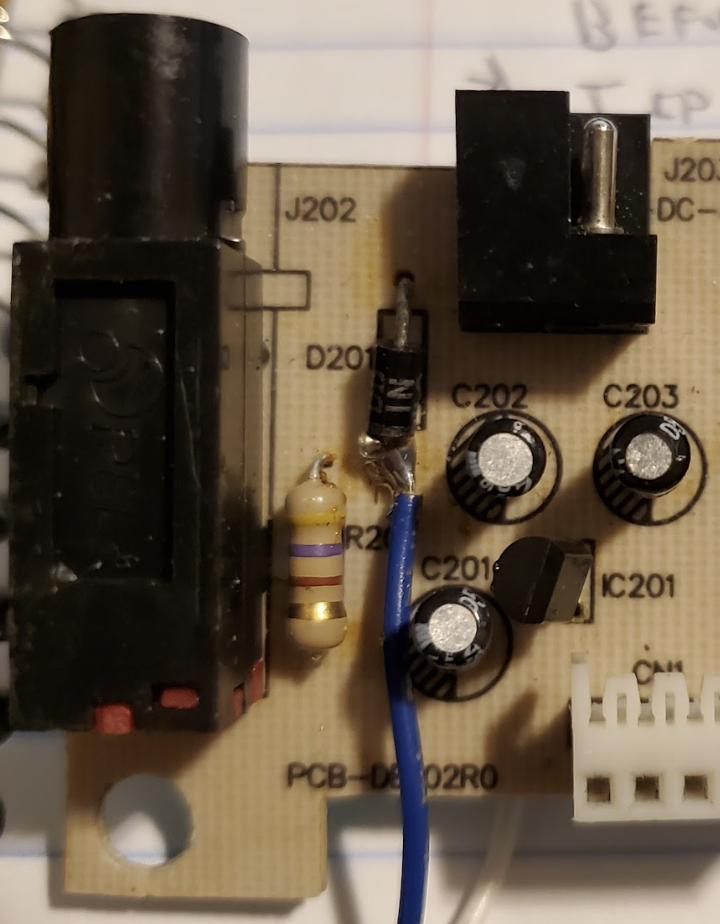
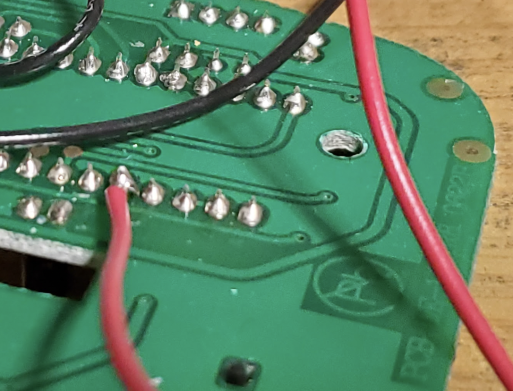
9. Connect the Power Wiring
The ground connection for the LFO Mod can be taken from one of the grounded lugs of the potentiometers.
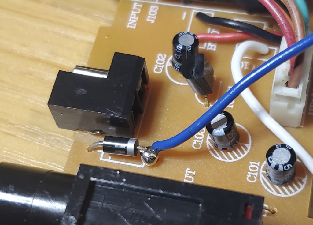
The 9Vdc power connection comes from the cathode of the protection diode on the daughter board.
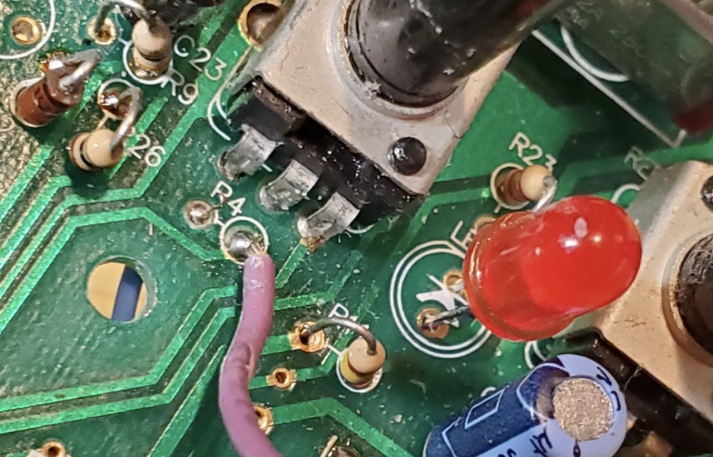
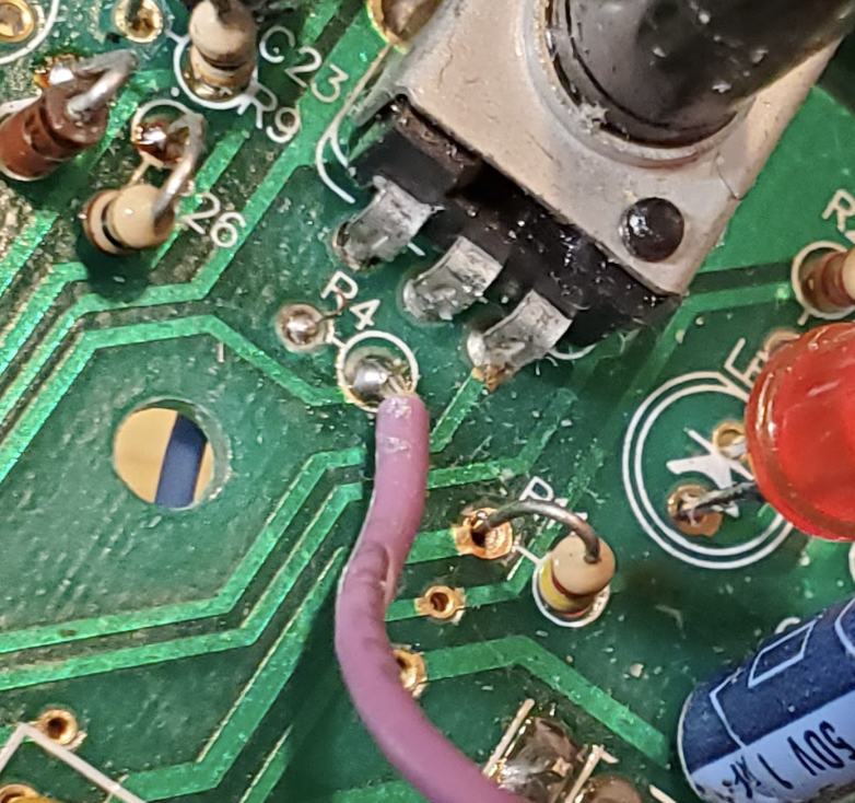
10. Remove resistor R4 (820 Ω)
Next, we need to remove the resistor R4. You can find it directly next to the LED and Speed potentiometer.
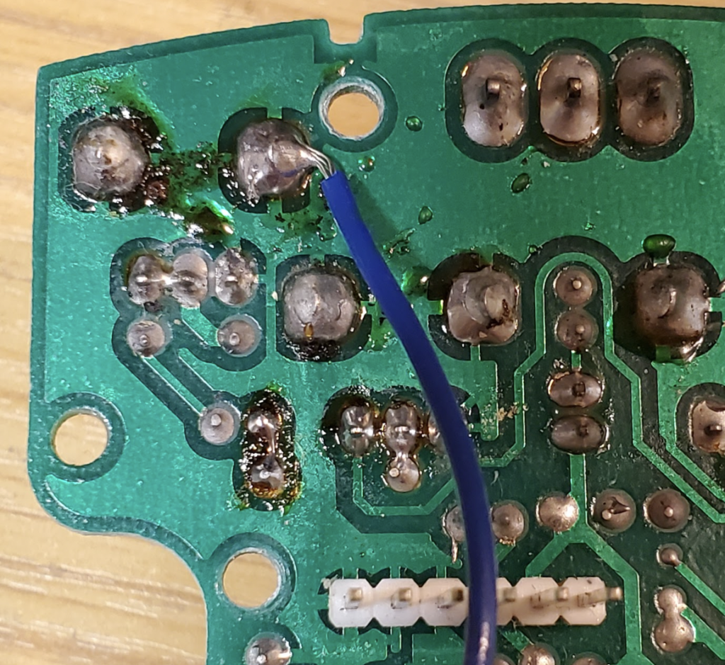
11. Connect the LDR Circuit to the DE-1 Board
Now we need to hook up our LDR modification board to the main circuit board. Refer to the schematic below as a reminder. We’ll be connecting one wire to the common/central terminal of the LFO Enable switch and the other wire to the LDR circuit.
You can connect both wires to the solder holes of where R4 used to be. I opted to use one of the vias on the component-side and solder the other side directly to the VR1 pot.
12. Mount the Controls
For mounting the controls, refer to the color-coded diagram from step 8.
Instructions for Surface-Mount Version
This section covers the rest of the steps related to the surface-mount version of the Dan-Echo. If you are modifying the through-hole version, jump to the Instructions for the Through-Hole Version.
9. Connect the Power Wiring
The ground connection for the LFO Mod can be taken from one of the grounded lugs of the potentiometers.
The 9Vdc power connection comes from the cathode of the protection diode on the daughter board.
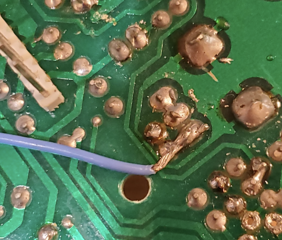
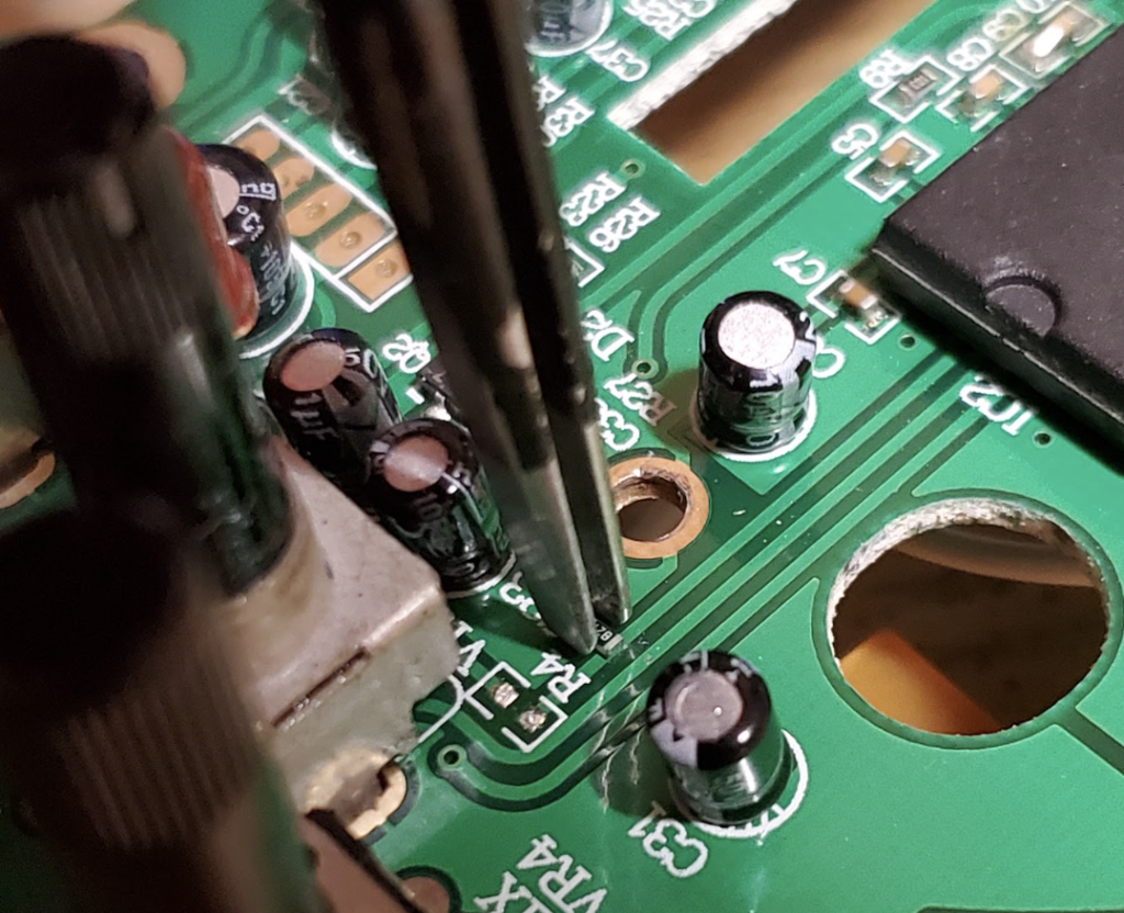
10. Remove resistor R4 (820 Ω)
Next, we need to remove the resistor R4. You can find it directly next to VR1, which is the Speed potentiometer.
The best tool to use for removing R4 is a hot air station alongside a good pair of precision tweezers.
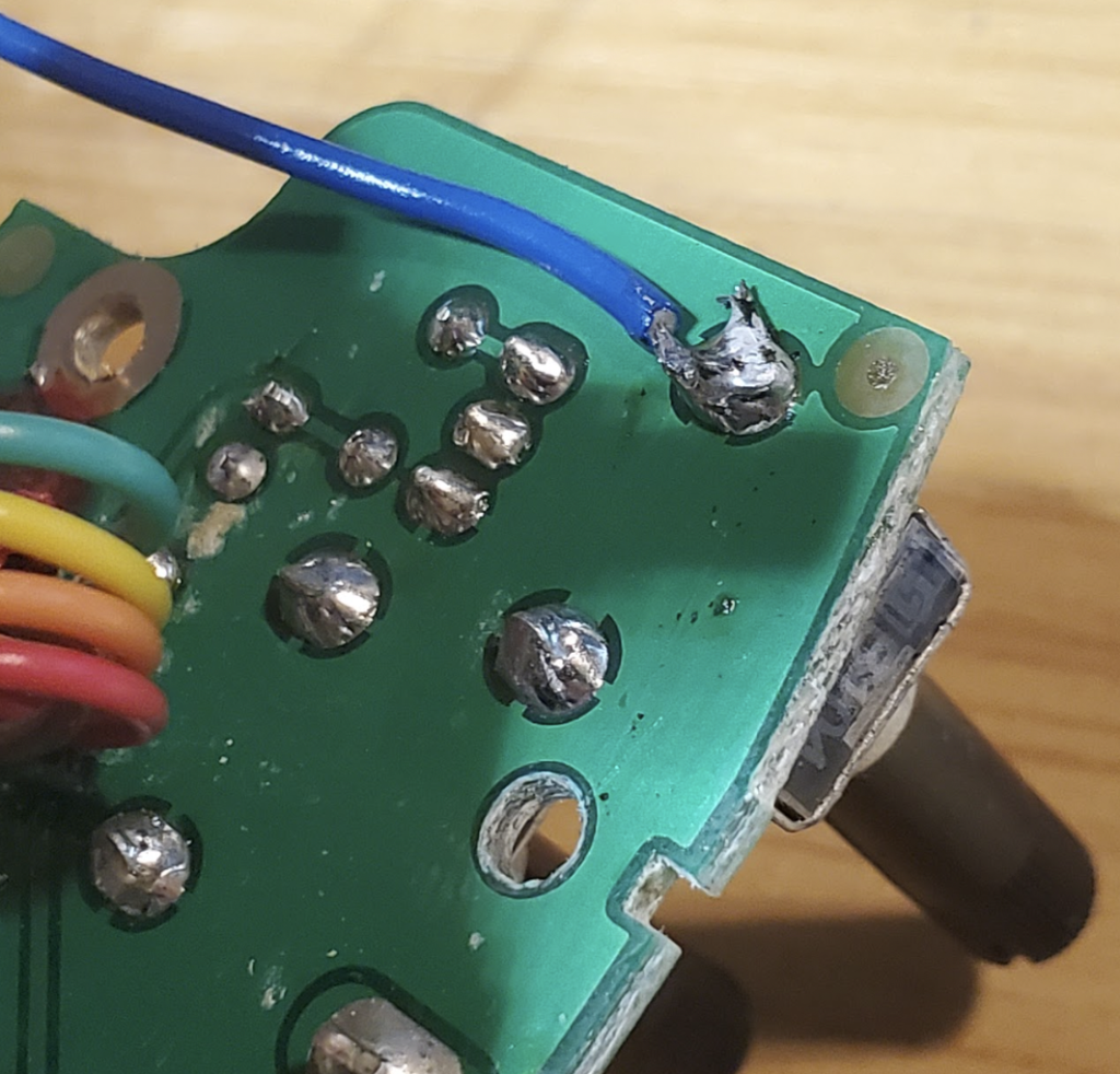
11. Connect the LDR Circuit to the DE-1 Board
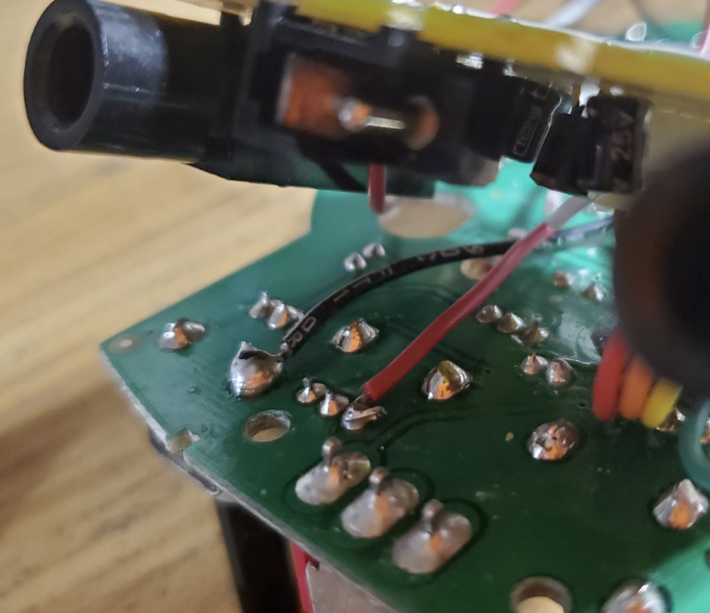
Now we need to hook up our LDR modification board to the main circuit board. Refer to the schematic below as a reminder. We’ll be connecting one wire to the common/central terminal of the LFO Enable switch and the other wire to the LDR circuit.
One of these wires can connect to pin 25 of the PT2395 chip. The other wire hooks up to the first lug of the VR1 Speed control potentiometer. See below for a visual.
12. Mount the Controls
For mounting the controls, refer to the color-coded diagram from step 8.
Dan-Echo LFO Mod Sample
While I have yet to record an audio sample, I do have a video of the modification breadboarded and working. See the trimmed video below to hear the LFO Mod in action.
Meet the Author:

Hi, I’m Dominic. By day, I’m an engineer. By night, I repair and modify guitar effects! Since 2017, I’ve been independently modifying and repairing guitar effects and audio equipment under Mimmotronics Effects in Western New York. After coming out with a series of guitar effects development boards, I decided the next step is to support that community through content on what I’ve learned through the years. Writing about electronics gives me great joy, particularly because I love seeing what others do with the knowledge they gain about guitar effects and audio circuits. Feel free to reach out using the contact form!
The Tools I Use
As a member of Amazon Associates, Stompbox Electronics earns and is supported by qualifying purchases.


