
The Dan-Echo DE-1 is a delay pedal built by Danelectro. It is based on the PT2395 echo chip, a Princeton Technology Corp predecessor to the famous PT2399.
While the DE-1 is relatively versatile, there are limitations. Luckily, the circuit lends itself to some interesting modification opportunities. Here are 5 Danelectro Dan-Echo Modifications that will both enhance and expand its’ functionality.

As a member of the Reverb Partner Program, eBay Partner Network, and as an Amazon Associate, StompboxElectronics earns from, and is supported by, qualifying purchases.
Disclaimer: Stompbox Electronics and/or the author of this article is/are not responsible for any mishaps that occur as a result of applying this content. All schematics shown here are excerpts from the original tracer, Mr. Basoni from March 28th, 2013.
1. Dan-Echo Doubler Mod
The Delay Time control has a decent upper limit, but the lower limit is not quite fast enough. The Doubler Mod was developed to allow the Dan-Echo to achieve the “doubling” delay effect by extending the lower range of the Delay Time control.
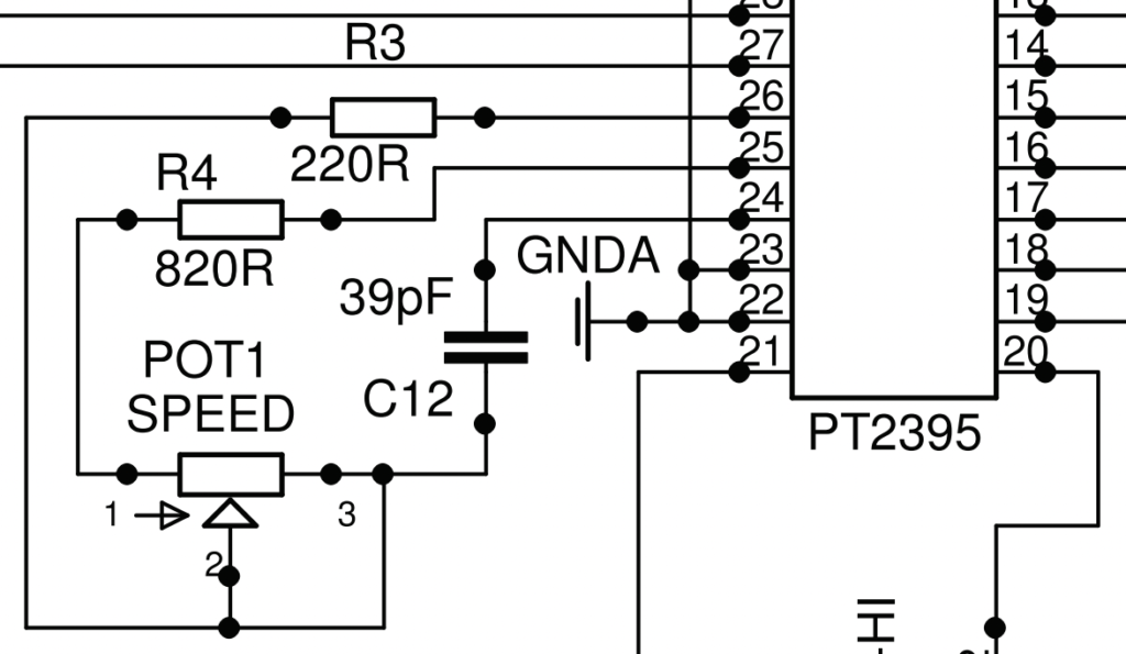
PT2395 Oscillator Speed Control
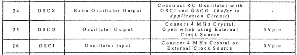
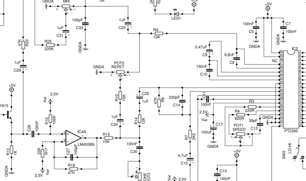
The Delay Time for the PT2395 is setup with an RC Oscillator using pins 24, 25, and 26. For the Dan-Echo, the related parts include R3 (220 Ω), POT1 (SPEED), R4 (820 Ω) and C12 (39 pF).
About the Doubler Mod
In the “1” position, the SPEED potentiometer resistance is bypassed, which is when the shortest delay time is heard. The Doubler Mod involves removing the resistor R4 and replacing it with a lower resistance.
Doubler Mod Audio Samples
Here’s a clip of the Dan-Echo prior to performing the Doubler Mod, with the Delay Time control set to it’s lowest setting:
And after performing the Doubler Mod:
2. Dan-Echo Hold Mod
The Hold Mod involves halting the operation of the delay circuit so that only the most immediate sample is repeatedly accessed. Circuit benders and drone lovers will love this mod.
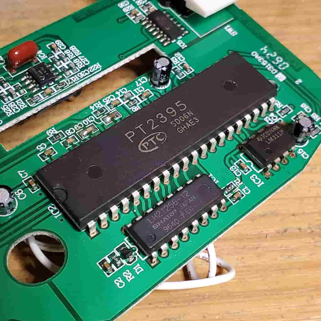
PT2395 – DRAM Circuit
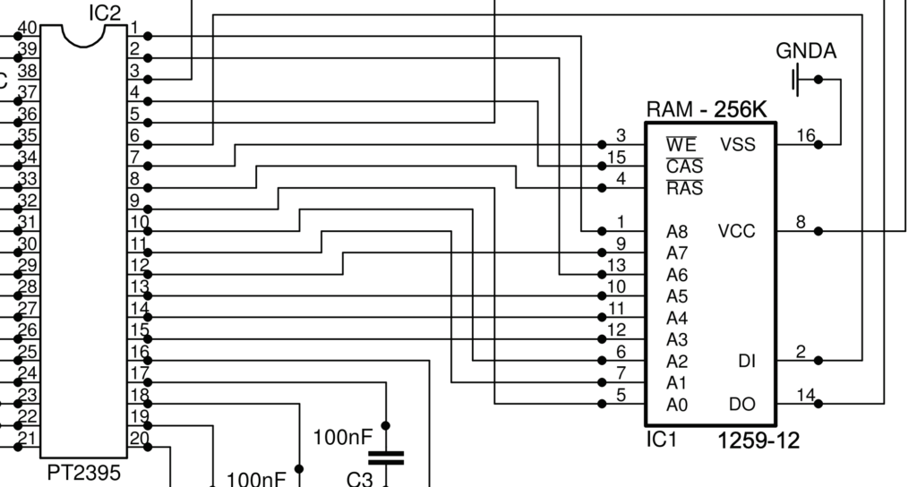
Dan-Echo’s PT2395 chip works in tandem with a DRAM chip situated directly next to it. It operates by addressing the DRAM with 9 bits (A0 through A8) and writing the processed analog value of the guitar signal to that address through the DI input on the DRAM (pin 2).
After one full cycle of addressing (set by the Delay Time control) the DRAM chip starts sending the saved data back into the PT2395. The digital signal travels from the DRAM Data Out (DO, pin 14) into the Memory Data Input “MDI” (pin 3) of the PT2395.
About the Hold Mod
The DRAM’s Write Enable (pin 3) is controlled by the PT2395’s pin 7. Disconnecting this control signal stops the PT2395’s ability to save an analog signal into the DRAM. That means the same data is accessed on every recall, resulting in a droning effect.
The mod only affects the writing of data to the DRAM. So, you can manipulate the droning output signal with the Delay Time and Tone controls just as you could under normal operation.
You can salvage the stock mode by using a toggle switch. That way you can “lift” the Write Enable and switch it back into stock mode when done.
Hold Mod Audio Sample
Here’s the Hold Mod in action:
3. Dan-Echo Infinite Repeats Mod
This one is often called the “R10” mod. The Dan-Echo doesn’t naturally allow itself to enter into self-oscillation. The Infinite Repeats mod lets you expand the Repeats knob into infinity.
The Dan-Echo Repeats Circuit
Below is the part of the circuit responsible for the Repeats control. Note that R10 (15kΩ) connects to the wiper of POT2 (Repeats). The Repeats knob is adjusted to feed the delayed signal (from pin 36/37 of the PT2395) back into the delay chip’s input (pin 31).
About the Infinite Repeats Mod
The resistor R10 serves as a maximum limit for how much signal can be fed back into the echo chip. Some modders exploit this part of the circuit by jumping the resistor with a toggle switch. As a result, it allows you to quickly induce infinite repeats.
Others simply lower the resistance of R10 so the range of the Repeats knob becomes wider.
Infinite Repeats Audio Sample
Take a quick listen to the following audio sample for the Dan-Echo Infinite Repeats mod. It starts relatively slow, but near the end picks up on the repeats.
4. Dan-Echo Buffer Mod
Input impedance is the resistance that an AC signal experiences as it travels through a circuit’s input. If the input impedance is too low, the signal could become attenuated. In the case of guitar effects, it results in the phenomena called “tone suck”.
Dan-Echo Input Impedance
According to Jürgen Müller, the input impedance of the Dan-Echo is about 100kΩ. That’s not great! In fact, it’s low enough to experience “tone suck,” especially when plugging your guitar directly into the input. A more commonly accepted input impedance would be anything from 1MΩ upwards.
Enter: the buffer.
The Buffer Circuit
A buffer circuit, by definition, has a high input impedance and low output impedance. Operational amplifiers (op amps) are naturally great candidates for this application, since they easily achieve these characteristics.
Below is a simple buffer circuit, built using an operational amplifier. V+ represents the supply voltage, while the triangular symbol is ground. The guitar signal input enters the non-inverting terminal. The output, signified by OUT, is fed back to the inverting input – a requirement for the buffer to operate correctly.
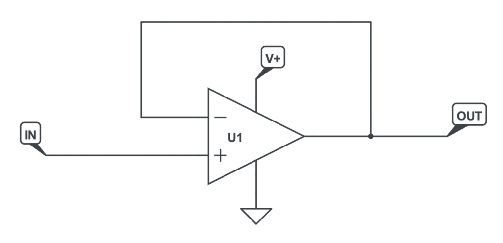
The input, IN, should be understood as an AC signal that is superimposed on a DC bias level which is half the V+ value.
About the Buffer Mod
The buffer mod is well documented and a few different versions can be found on the internet. The most thorough and correct I’ve seen so far is detailed in Jürgen Müller’s article, linked above. Others involve adding in a vero-boarded op amp buffer circuit and connecting it to the daughter board with some hook-up wire (see this forum post). Both approaches work, so feel free to choose whichever you find most accessible.
5. Dan-Echo LFO Mod
Many great delay effects pedals have the ability to modulate delay time, emulating the sound of a warped vinyl record or a slightly loose tape deck. These delay effects generally have a low-frequency oscillator circuit for doing just that.
A low-frequency oscillator (LFO) is an oscillator that operates in the sub-audio range (under 20 Hz). In guitar effects, LFOs have been historically used as a source of modulation. Tremolo effects use it for modulating the amplitude, while Phaser effects use it to modulate Phase. Chorus and Vibrato use LFOs for oscillating the frequency characteristic.
The DE-1 is a simple delay and has no such oscillator. But we can modify the Dan-Echo circuit to include a source of modulation.
Relaxation Oscillators
The relaxation oscillator is a type of oscillator that uses hysteresis as the basis for modulation. It produces two types of signals: square and triangle. If you’ve taken a stroll through your share of BOSS schematics you’ve probably come across a relaxation oscillator or two.
BOSS TR-2 LFO Example
Below is an example LFO from the TR-2 schematic:
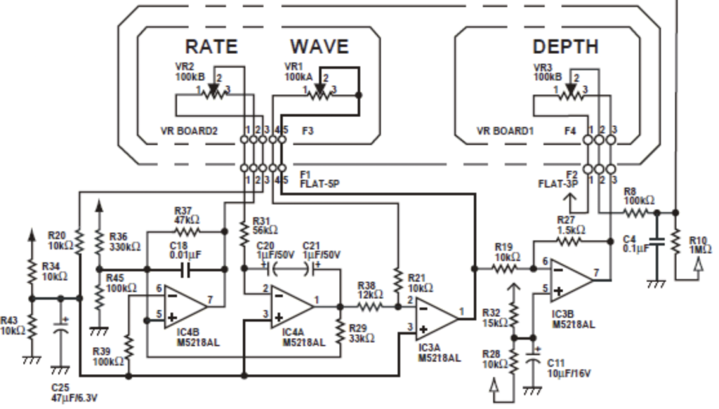
You will see there are two controls that are directly related to the LFO: Rate and Wave.
There are also four op amps shown. The first, IC4B, is configured as an op amp comparator with hysteresis. IC4A is an op amp integrator, and the Rate knob adjusts how “fast” it integrates. IC3A is configured as an inverting amplifier, with the Wave knob adjusting the gain. Likewise, IC3B is also an inverting amplifier and is driving a Voltage-Controlled Amplifier (not pictured).
The Depth simply adjusts the level of attenuation on the output.
There are much simpler relaxation oscillators you can build. In fact, I built a calculator for helping you do just that:
About the LFO Mod
You can insert an LFO into the PT2395 circuit by utilizing an LDR (light-dependent resistor) and an LED. By driving the LED, you can modulate the resistance of the LDR, which can be put either in series with R4 or in place of it.
If the goal is to totally remove R4, then you can also install an LFO enable switch. One direction takes out R4 and replaces it with a connection to the LDR. The other direction takes out the LDR and replaces that with R4 (back to stock mode).
LFO Mod Audio Sample
While I never made an audio recording of the LFO mod, I do have a video of it breadboarded and working:
Meet the Author:

Hi, I’m Dominic. By day, I’m an engineer. By night, I repair and modify guitar effects! Since 2017, I’ve been independently modifying and repairing guitar effects and audio equipment under Mimmotronics Effects in Western New York. After coming out with a series of guitar effects development boards, I decided the next step is to support that community through content on what I’ve learned through the years. Writing about electronics gives me great joy, particularly because I love seeing what others do with the knowledge they gain about guitar effects and audio circuits. Feel free to reach out using the contact form!
The Tools I Use
As a member of Amazon Associates, Stompbox Electronics earns and is supported by qualifying purchases.


