
The Dan-Echo Hold mod is a modification that allows you to lock in forced oscillations.
The Dan-Echo produces delay by saving your guitar’s signal into a memory chip, then recalling it some milliseconds later. It does this over, and over, and over, and…you get the picture!
The Hold mod adds a toggle switch that, when switched ON, prevents the storing of new signal information into the Dan-Echo’s memory chip. Therefore, the data in the memory chip is “held” and replayed over and over again until the switch is back into the normal position where new signal information can be stored.
In this post, we go over the Dan-Echo Hold modification and how you can apply it to your Dan-Echo!

As a member of the Reverb Partner Program, eBay Partner Network, and as an Amazon Associate, StompboxElectronics earns from, and is supported by, qualifying purchases.
Disclaimer: Stompbox Electronics and/or the author of this article is/are not responsible for any mishaps that occur as a result of applying this content.
The schematics shown here are excerpts from the original tracer, Mr. Basoni from March 28th, 2013.
Compatible Versions
The Hold Mod is known to be compatible with both through-hole and surface-mount versions of the Danelectro Dan-Echo.
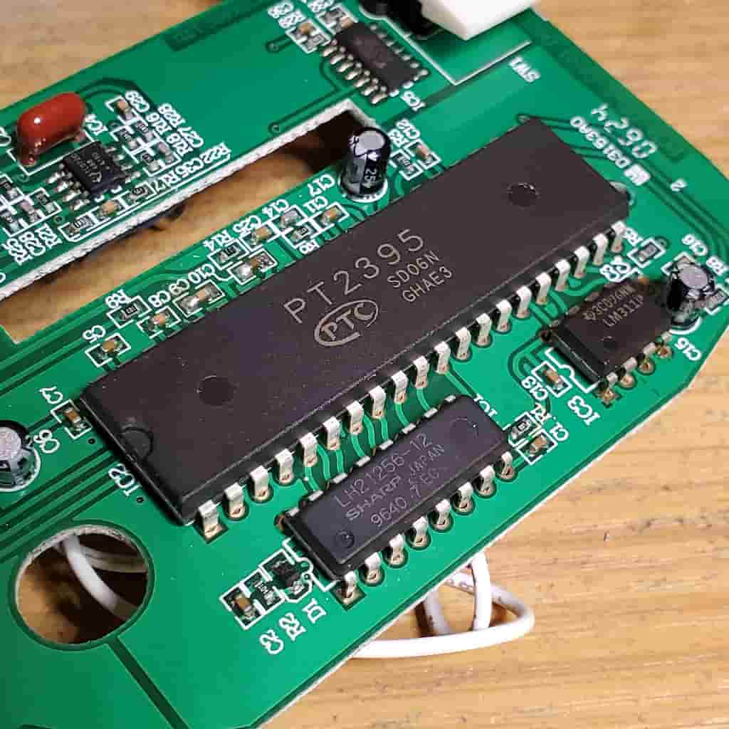
There is at least one surface-mount version of the Dan-Echo that doesn’t have a PT2395. This modification is only verified for versions of the Dan-Echo that have the PT2395 chip. Unfortunately there is no way to know which version of the Dan-Echo you have unless you open it up and look at the circuit board.
If your Dan-Echo has the large PT2395 chip shown below, you’re good to go!
Required Tools for the Dan-Echo Hold Mod
Standard tools typical of guitar pedal modifications are required to carry out the Hold Mod. These instructions assume you have the knowledge to operate the tools and carry out the modification without doing harm to your Dan-Echo.
| Tool | Recommendation | Where to Find |
|---|---|---|
| Soldering Station/Iron | Weller Digital Soldering Station – WE1010NA | Amazon | eBay |
| Solder | Kester Solder 24-6040-0027 | Amazon | eBay |
| Wire Strippers | Klein Tools 11063W Wire Cutter / Wire Stripper, Heavy Duty Automatic Wire Stripper Tool | Amazon | eBay |
| Precision Tweezers | 6PCS Precision Tweezers Set | Amazon | eBay |
| Xacto Knife | Elmer’s X-ACTO X3311 N0. 1 Precision Knife | Amazon | eBay |
| Drill Press | 10 in. Bench Mount Drill Press, 12 Speed by Central Machinery | Amazon | eBay |
| Drill Bit Set | DEWALT Titanium Nitride Coated Drill Bit Set with Pilot Point | Amazon | eBay |
| Automatic Center Punch | Automatic Center Punch, Pamiso 5.1 Inch Spring Loaded Drill Punch Tool | Amazon | eBay |
| Deburring Tool | General Tools 196 Short Length Hand Reamer & Countersink, 3/4″ | Amazon | eBay |
Required Parts for the Dan-Echo Hold Mod
For the Hold Mod, you will need the ON-ON toggle switch in the table below, along with some wire for connecting the switch to the board.
Parts List
| Part | Qty | Description | Where to Find |
|---|---|---|---|
| ON-ON Toggle Switch | 1 | Taiway SPDT On On Switch – Solder Lug – Short Shaft | LoveMySwitches |
Dan-Echo Hold Mod Instructions
The Hold Mod is generally the same for both through-hole and surface-mount versions. Follow these instructions to carry out the Hold mod.
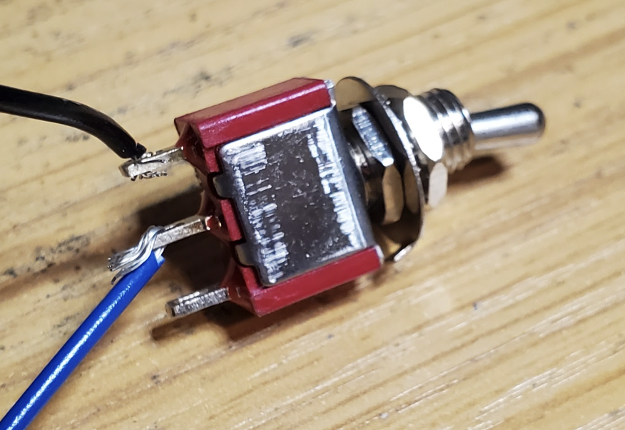
1. Prepare the Toggle Switch
The first step is to prepare the toggle switch. Cut and strip two wires that are long enough to reach from the toggle switch to the circuit board.
One wire should be connected to the common (middle) lug. The second wire connects to one of the two outside lugs.
2. Sever the Write Enable Trace
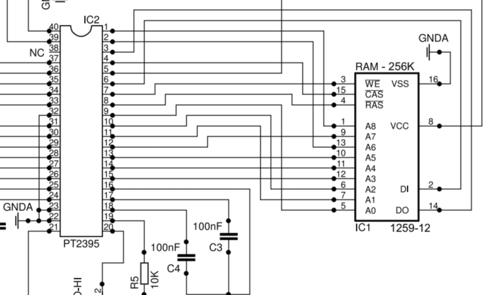
The schematic below shows that the Write Enable on the DRAM chip is pin 3. The PT2395 sends a write enable command from pin 7. The copper trace between those two points needs to be severed to complete the modifcation. I’ve found that the best way to do it is with an Xacto knife.
This is one of the most important steps of the modification. Pay very close attention and be focused, because you can easily screw up here and accidentally sever the wrong trace.
3. Solder the Toggle Switch Wires
Now it’s time to solder the wires from the toggle switch to the circuit board. The wires can be soldered directly to the pins on the solder-side of the board.
One of the wires is soldered to pin 3 of the DRAM chip. The other wire is soldered to pin 7 of the PT2395 chip.
4. Drill and Mount the Toggle Switch
Finally, we’ll need to install the new toggle switch. You’ll first need to drill into the enclosure, so make sure the placement of the switch works for you.
I’ve found that one of the better places to mount the switch is just over the battery compartment. But, in order to place it there, you’ll need to scrape out the foam that keeps in the battery. I usually use an Xacto knife.
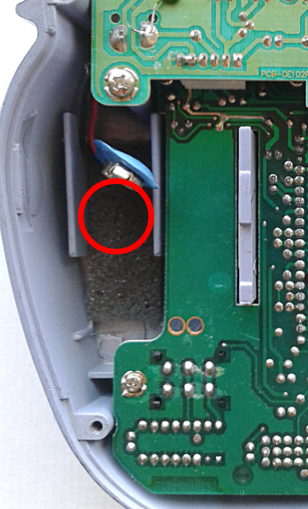
This position makes it impossible to use a standard 9V battery with the Dan-Echo. I didn’t mind this, since the Dan-Echo doesn’t have good battery life. That said, if you would like to still be able to use a 9V battery with the Dan-Echo you can opt to place it just next to the battery compartment. As long as you use the recommended toggle switch, it should fit.
Dan-Echo Hold Mod Audio Sample
Below is an audio sample I took of the Hold Mod in action. The sounds are almost helicopter-like but you can achieve much more depending on what happens to be stored in the memory chip at the time you flip the toggle switch. Throughout the clip you can hear me playing with the Speed and Tone controls.
Meet the Author:

Hi, I’m Dominic. By day, I’m an engineer. By night, I repair and modify guitar effects! Since 2017, I’ve been independently modifying and repairing guitar effects and audio equipment under Mimmotronics Effects in Western New York. After coming out with a series of guitar effects development boards, I decided the next step is to support that community through content on what I’ve learned through the years. Writing about electronics gives me great joy, particularly because I love seeing what others do with the knowledge they gain about guitar effects and audio circuits. Feel free to reach out using the contact form!
The Tools I Use
As a member of Amazon Associates, Stompbox Electronics earns and is supported by qualifying purchases.


