
The Dan Echo’s Delay Time control has a decent upper limit, but the lower limit is not quite fast enough for my taste. The Doubler Mod was developed to allow the Dan-Echo to achieve the “doubling” delay effect by extending the lower range of the Delay Time control.
Put another way: “Doubling” is a trick used to make a guitar sound “thicker”, either in live settings with a pedal or during recording. By slightly delaying the guitar signal you can achieve a layered sound. The Doubler Mod enhances the Dan-Echo by giving you this ability.

As a member of the Reverb Partner Program, eBay Partner Network, and as an Amazon Associate, StompboxElectronics earns from, and is supported by, qualifying purchases.
Disclaimer: Stompbox Electronics and/or the author of this article is/are not responsible for any mishaps that occur as a result of applying this content.
The schematics shown here are excerpts from the original tracer, Mr. Basoni from March 28th, 2013.
Compatible Versions
This modification is compatible with both the through-hole and surface-mount version of the Dan-Echo.
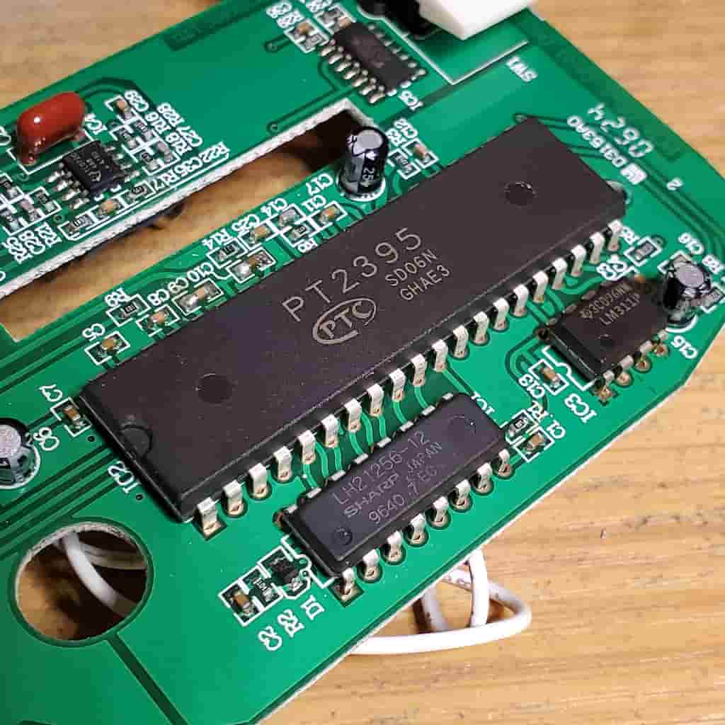
There is one surface-mount version of the Dan-Echo that does not use the PT2395. That version is not compatible with the Doubler Mod, so please check whether your Dan-Echo circuit has the PT2395 echo chip before starting.
Required Tools for the Dan-Echo Doubler Mod
Standard tools typical of guitar pedal modifications are required to carry out the Doubler Modification. These instructions assume you have the knowledge to operate the tools and carry out the modification without doing harm to your Dan-Echo.
| Tool | Recommendation | Where to Find |
|---|---|---|
| Soldering Station/Iron | Weller Digital Soldering Station – WE1010NA | Amazon | eBay |
| Solder | Kester Solder 24-6040-0027 | Amazon | eBay |
| Wire Strippers | Klein Tools 11063W Wire Cutter / Wire Stripper, Heavy Duty Automatic Wire Stripper Tool | Amazon | eBay |
| Precision Tweezers | 6PCS Precision Tweezers Set | Amazon | eBay |
| Drill Press | 10 in. Bench Mount Drill Press, 12 Speed by Central Machinery | Amazon | eBay |
| Drill Bit Set | DEWALT Titanium Nitride Coated Drill Bit Set with Pilot Point | Amazon | eBay |
| Automatic Center Punch | Automatic Center Punch, Pamiso 5.1 Inch Spring Loaded Drill Punch Tool | Amazon | eBay |
| Deburring Tool | General Tools 196 Short Length Hand Reamer & Countersink, 3/4″ | Amazon | eBay |
Surface-Mount Version
In order to modify the surface-mount version, the best tool to have is a hot-air desoldering station. Having a hot air station will help you desolder surface-mount components.

Required Parts for the Dan-Echo Doubler Mod
The parts will be the same for both the through-hole and surface-mount versions of the Doubler Mod.
If you would like to purchase a general parts kit instead of purchasing parts individually I can recommend a resistor kit. It has the value needed for the Doubler Mod along with many others you’ll need in your DIY modding endeavors.
Parts List
Below is a list of the required parts for the Doubler Mod:
| Part | Qty | Description | Where to Find |
|---|---|---|---|
| 470 Ω Resistor | 1 | 470 OHM 1/8W 1% METAL FILM RESISTOR | Tayda |
| 820 Ω Resistor | 1 | 820 OHM 1/8W 1% METAL FILM RESISTOR | Tayda |
| ON-ON Toggle Switch | 1 | Taiway SPDT On On Switch – Solder Lug – Short Shaft | LoveMySwitches |
| Heatshrink | – | Heat Shrink Tubing Kit | Amazon | eBay |
Dan-Echo Doubler Mod Instructions
For both versions, the Doubler Mod is generally the same. Only the steps involving the circuit board itself change.
Depending on where you decide to mount the toggle switch, the Doubler Mod might make it so you can’t use a battery with the pedal. This isn’t a huge problem, since the Dan-Echo drains the battery quickly anyway. Just note that if you still want to use the battery, you can do so by mounting the toggle switch in a different position.
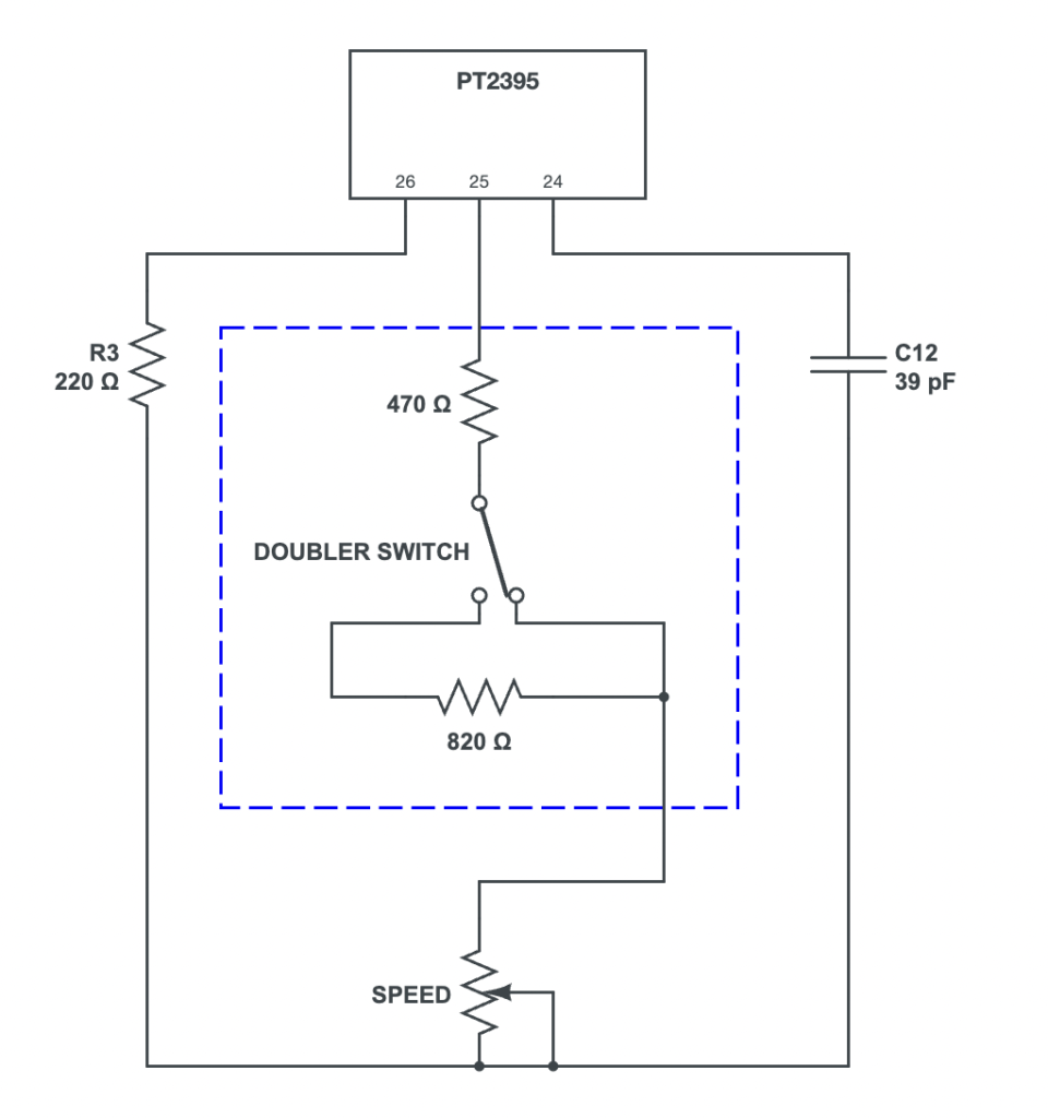
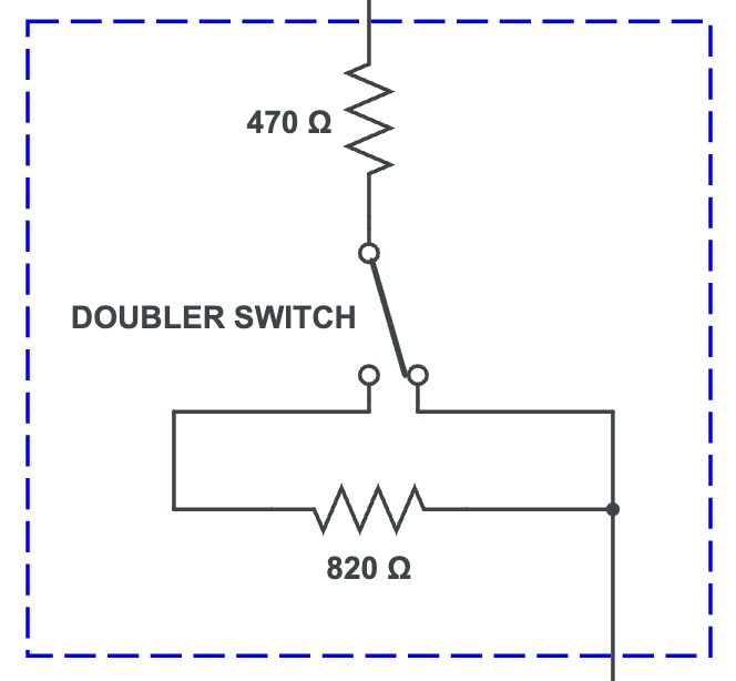
Throughout the mod please refer to the following schematic diagram. R3, C12 and the SPEED potentiometer are stock parts on the Dan-Echo circuit board. Everything in the blue dashed line relates to the modification.
1. Remove R4
This step differs between the through-hole and surface-mount versions of the Dan-Echo. First we’ll go over what to do if you have the through-hole version. Then, we’ll take a look at the surface-mount version.
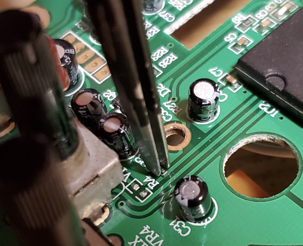
Removing R4 from the Through-Hole Version
For the through-hole version, removing R4 involves heating up one or both of the solder pads and removing the part with a pair of precision tweezers.
After removing the resistor, be sure to use a desoldering pump to remove the solder.
Removing R4 from the Surface-Mount Version
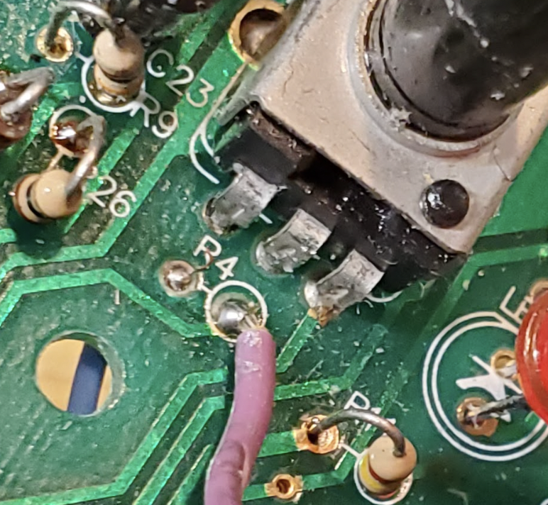
On the surface-mount version, you can find R4 directly next to VR1, which is the Speed potentiometer.
The best tool to use for removing R4 is a hot air station alongside a good pair of precision tweezers.
2. Prepare the Toggle Switch
Now we need to prepare the wiring for the toggle switch. We need to make two wires, based on the schematic below.
The first (top) wire includes a 470 ohm resistor in series. One end of the resistor is tied to the common lug, and the other will be connected to the circuit board.
The second (bottom) wire will connect to one of the outside switch lugs. Make sure you also solder the 820 ohm resistor across the outside lugs, as shown below.
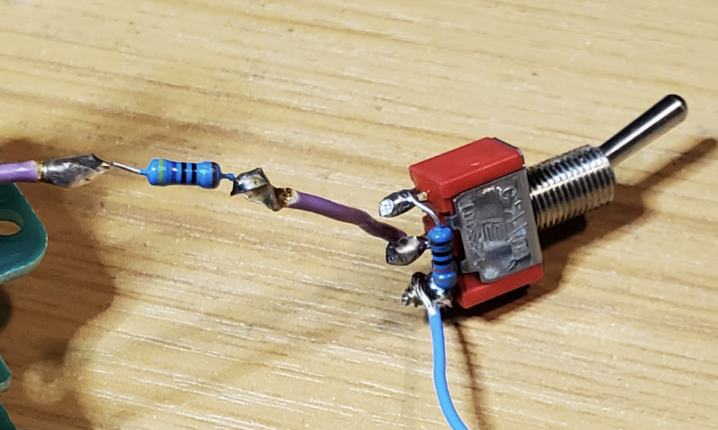
Use a heat shrink to insulate the 470 ohm resistor (not shown in the photo).
3. Solder the Toggle Switch Connections
Soldering the Toggle Switch on the Through-Hole Version
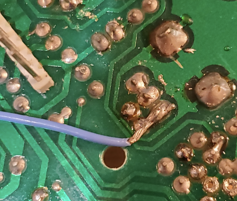
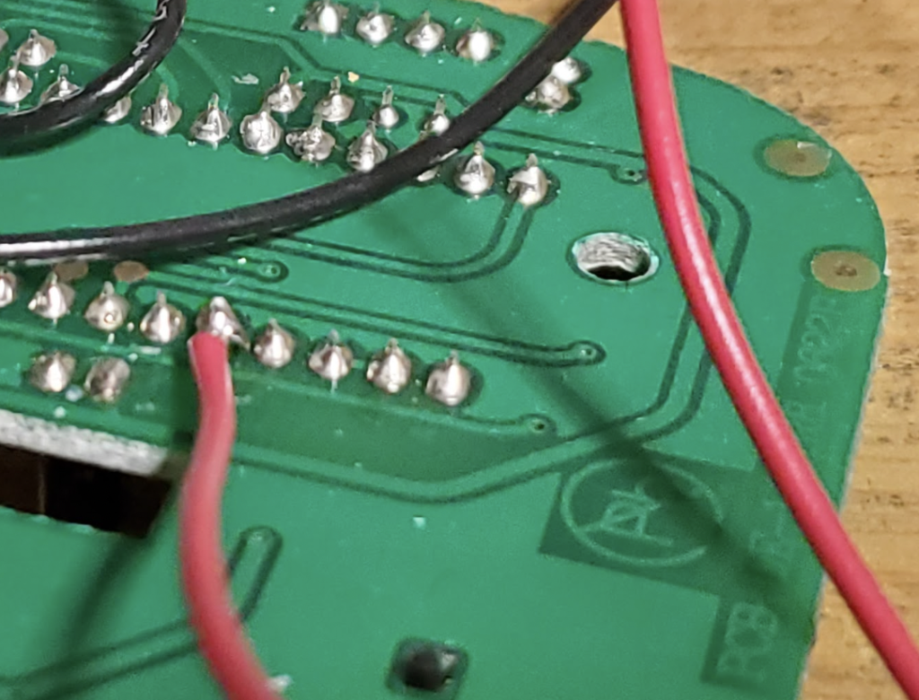
For the through-hole version, you can use the two solder holes that were exposed after removing R4.
I personally use only one of the solder holes. The other wire gets soldered to the other side, as shown below.
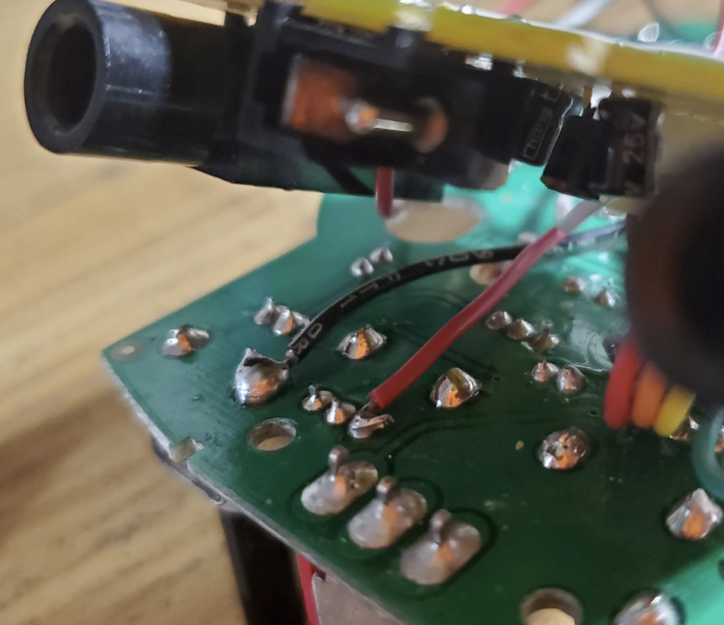
Soldering the Toggle Switch on the Surface-Mount Version
For the surface-mount version, the connection points are different. One wire from the toggle switch is connected to pin 25 of the PT2395 chip. The other wire is connected to one of the lugs on the Speed potentiometer shown below.
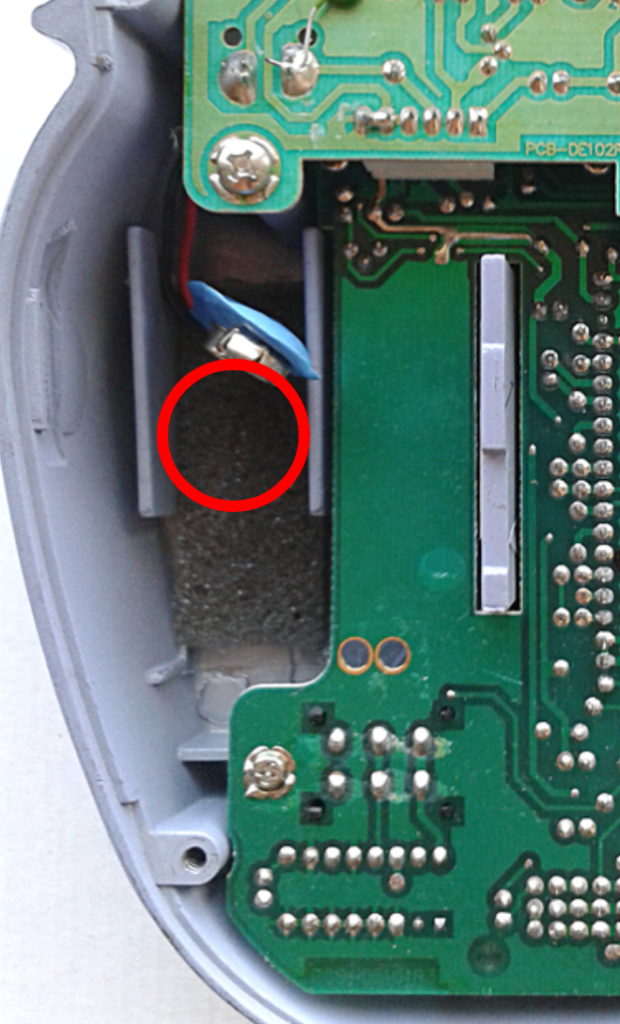
4. Drill and Mount the Toggle Switch
Next, we’ll need to install the new toggle switch. I’ve found that one of the better places to mount it is just over the battery compartment. But, in order to place it there, you’ll need to scrape out the foam that keeps in the battery. I usually use an Xacto knife.
Dan-Echo Doubler Mod Audio Sample
Here’s a clip of the Dan-Echo prior to performing the Doubler Mod, with the Delay Time control set to it’s lowest setting:
And after performing the Doubler Mod:
Meet the Author:

Hi, I’m Dominic. By day, I’m an engineer. By night, I repair and modify guitar effects! Since 2017, I’ve been independently modifying and repairing guitar effects and audio equipment under Mimmotronics Effects in Western New York. After coming out with a series of guitar effects development boards, I decided the next step is to support that community through content on what I’ve learned through the years. Writing about electronics gives me great joy, particularly because I love seeing what others do with the knowledge they gain about guitar effects and audio circuits. Feel free to reach out using the contact form!
The Tools I Use
As a member of Amazon Associates, Stompbox Electronics earns and is supported by qualifying purchases.


