[Last Updated: January 20, 2024]
Welcome back to another exciting installment of our blog series on guitar effects pedal circuit design! Today, we’re diving into a crucial yet often underestimated aspect of building guitar pedals – the power supply.
Imagine the power supply as the heartbeat of your pedal, providing the lifeblood for each note and effect to come alive. The stability and cleanliness of this power source play a pivotal role in shaping the overall sound quality and performance of your guitar effects pedal.
In this post, we’ll be shining a spotlight on a key player in the world of power regulation – the linear voltage regulator. Think of it as the unsung hero quietly ensuring that your pedal receives a consistent and clean flow of power, allowing your creativity to flourish without any unwanted hums or disruptions.
As a member of the Reverb Partner Program and as an Amazon Associate, StompboxElectronics earns from, and is supported by, qualifying purchases.
Disclaimer: Stompbox Electronics and/or the author of this article is/are not responsible for any mishaps that occur as a result of applying this content.
What is a Linear Voltage Regulator?
A linear voltage regulator’s primary function is to maintain a consistent voltage level at it’s output. It acts as a reliable gatekeeper that shields your circuit from the chaos of variable input voltages and unpredictable load conditions. Like a seasoned chef adjusting the recipe on the fly – a linear regulator adapts to the situation, tweaking its internal components to ensure a smooth and consistent output voltage.
How Does a Linear Voltage Regulator work?
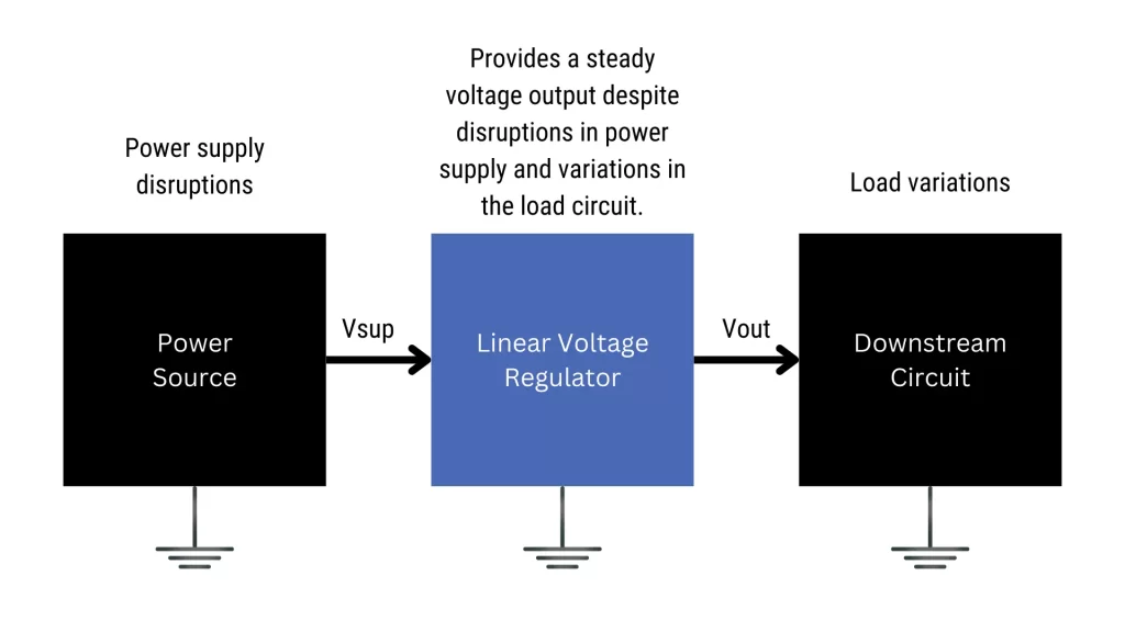
A linear voltage regulator operates on the principle of feedback control to maintain a constant output voltage despite variations in the input voltage and load conditions.
During operation, as the input voltage or load conditions change, an error amplifier sub-circuit continuously monitors the output and adjusts a “pass element” to maintain a constant voltage. This closed-loop feedback mechanism ensures that the output voltage remains within the specified tolerance, providing a stable and regulated power supply for the components downstream in the circuit.
Linear Voltage Regulators in Guitar Pedals
Most voltage regulation is performed outside of the guitar pedal in pedal power supply units. Some examples of pedal power supplies that employ linear voltage regulation include:
If you’re sticking to all-analog overdrives, boosts, fuzz and distortion pedals then you can probably get by without any knowledge of linear voltage regulators. Once you introduce digital circuits in your design, you will need to convert the standard power supply voltage down to the required digital voltage level.
For example, the PT2399 is a popular IC used for echo and delay circuits. The chip requires a supply voltage of 5V, but most pedals are powered with 9V and above. If you’re interested in building a circuit with a PT2399, you will need to regulate it’s supply voltage down to the required 5V level.
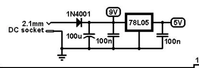
Below is an excerpt of the Small Time schematic from Valve Wizard. It shows a 78L05 (the “L” stands for low power) being used to supply the PT2399 with a clean, regulated 5V. You might recognize the first portion of the power circuit from Circuit 6: The Power Supply Filter.
Another example is with circuits involving microcontrollers. Microcontrollers are known to require either 5V or 3.3V, depending on the chip. If you’re using a microcontroller in your design, then you will need to use a voltage regulation circuit to regulate it’s supply voltage, and the linear regulator provides a simple way to do it.
Types of Linear Voltage Regulators
There are two main types of linear voltage regulators:
- Fixed-Voltage Regulators
- Adjustable-Voltage Regulators
In short, the main difference between them lies in the adjustability of the output voltage. Fixed regulators provide a straightforward solution for specific voltage requirements, while adjustable regulators offer flexibility for applications demanding non-standard output voltages.
The Fixed-Voltage Linear Regulator
A fixed-voltage linear regulator has a predefined and fixed output voltage. There is no way to change the expected output of a fixed-voltage linear regulator, as it’s decided by the manufacturer.
The internal circuitry of fixed-voltage regulators do not need much to accomplish the task. For that reason, fixed-voltage regulator ICs are easy to use “out of the box”.
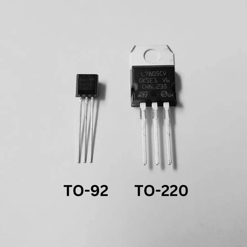
The 78xx family of ICs are the most common ICs used for linear voltage regulation in DIY pedal power circuits. They are simple 3-terminal devices with input, output and ground pins. Typically, they are found in through-hole (TO-220, TO-92) or surface-mount packages (SOT-23).
Some examples of linear voltage regulators are found in the table below, along with their nominal output voltage. We will focus on using the 7805 5V linear voltage regulator.
| 78xx Code | Nominal Output Voltage |
|---|---|
| 7805 | 5 V |
| 7808 | 8 V |
| 7809 | 9 V |
| 7812 | 12 V |
| 7815 | 15 V |
The Adjustable-Voltage Regulator
An adjustable-voltage linear regulator is an electronic device that maintains a stable output voltage, with the unique feature of allowing users to adjust the output within a specified range. This type of regulator is commonly employed in applications where flexibility in voltage settings is crucial.
The LM317, a well-known example of an adjustable-voltage linear regulator, is often used in electronic circuits, including guitar pedal power supplies.
Similar to the 78xx series, the LM317 operates as a three-terminal positive adjustable voltage regulator. It allows users to set the output voltage to a desired level by using a pair of external resistors. The LM317 is capable of providing output voltages in the range of 1.25V to 37V. It can be most commonly found in through-hole packages (TO-220 or TO-92) and surface-mount packages (SOT-23).
Fixed-Voltage Regulator Circuit
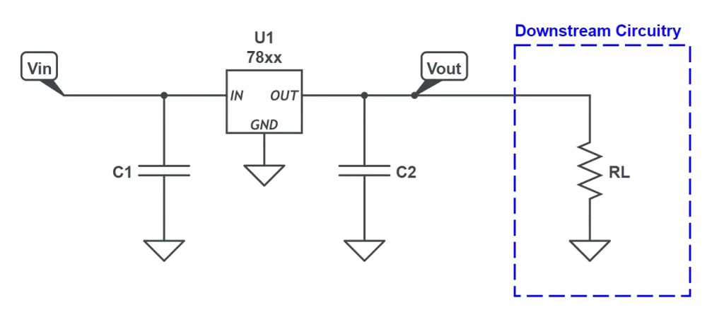
Now that you’re familiar with fixed-voltage linear regulators, let’s look at how to build one. There are 7 things required for a fixed-voltage regulator circuit to work. They are listed below, and visualized in the circuit shown in Figure 11.4.
- Fixed-Voltage Regulator IC (78xx family)
- Input Capacitor (C1)
- Output Capacitor (C2)
- Input Voltage (Vin)
- Ground (GND)
- Output Voltage (Vout)
- Load (RL)
Caution: Linear voltage regulators have a tendency to produce a lot of heat as their output current increases. As a rule of thumb, if your circuit draws over, say, 20mA then you are advised to use a heat sink in order to dissipate the heat. There are kits available on Amazon or Tayda specifically for heat sinking 78xx components.
Fixed-Voltage Regulator Parts List
Use the following parts to build a fixed 5V regulator for PT2399 circuits and microcontroller circuits:
| Parts | Qty |
|---|---|
| 7805 Linear Voltage Regulator | 1 |
| 100uF Electrolytic Capacitor | 1 |
| 47uF Electrolytic Capacitor | 1 |
| Heat Sink (optional) | 1 |
Adjustable-Voltage Regulator Circuit
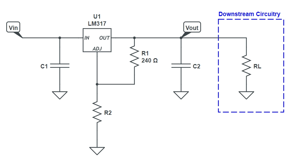
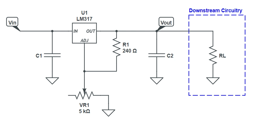
As you can imagine, constructing an adjustable-voltage linear regulator is not so different than building its fixed-voltage equivalent. You only need one more component: the adjustment resistor.
This can be in the form of two resistors (R1 and R2, shown in Figure 11.5) or in the form of a trimpot using a variable resistor configuration (shown in Figure 11.6).
Caution: Linear voltage regulators have a tendency to produce a lot of heat as their output current increases. As a rule of thumb, if your circuit draws over, say, 20mA then you are advised to use a heat sink in order to dissipate the heat. There are kits available on Amazon or Tayda specifically for heat sinking 78xx components.
Adjustable-Voltage Regulator Parts List
If you ever find the need for an adjustable-voltage regulator, here is a parts list for building it. Use this LM317 voltage regulator calculator for defining which resistor values (R1 and R2) you’ll need for a particular output voltage. Alternatively, you can use a trimpot in place of R2.
| Parts | Qty |
|---|---|
| LM317 Adjustable Regulator | 1 |
| 100uF Electrolytic Capacitor | 1 |
| 47uF Electrolytic Capacitor | 1 |
| Resistor R1 | 1 |
| Resistor R2 | 1 |
| Trimmer (in place of R2) | 1 |
| Heat Sink (optional under 20mA) | 1 |
Guitar Effects Design in 48 Circuits or Less
The 48 Circuits or Less article series serves to close the gap between DIY guitar effects design and guitarists interested in the craft by uniquely curating the most important aspects of DIY guitar effect circuit design. This post is part of the 48 Circuits or Less series. View more articles in this series here.
Meet the Author:

Hi, I’m Dominic. By day, I’m an engineer. By night, I repair and modify guitar effects! Since 2017, I’ve been independently modifying and repairing guitar effects and audio equipment under Mimmotronics Effects in Western New York. After coming out with a series of guitar effects development boards, I decided the next step is to support that community through content on what I’ve learned through the years. Writing about electronics gives me great joy, particularly because I love seeing what others do with the knowledge they gain about guitar effects and audio circuits. Feel free to reach out using the contact form!
The Tools I Use
As a member of Amazon Associates, Stompbox Electronics earns and is supported by qualifying purchases.


