
By: Dominic Sciarrino | Stompbox Electronics | Last Updated: March 22nd, 2026
Every component in a guitar effects pedal depends on a clean, stable DC voltage to function correctly. The power supply is where that voltage comes from, and understanding it from a design perspective is one of the most important foundations in effects pedal development. This article covers the full picture: the types of power sources a circuit may receive, polarity and connector standards, how to calculate and measure current draw, the noise problems introduced by shared power rails, how mains-powered pedals convert AC to DC internally, and the power supply filter circuit.
As a member of the Reverb Partner Program, eBay Partner Network, and as an Amazon Associate, StompboxElectronics earns from, and is supported by, qualifying purchases.
Disclaimer: Stompbox Electronics and/or the author of this article is/are not responsible for any mishaps that occur as a result of applying this content.
How Pedals Are Powered – A Guide
A builder needs to understand every type of power source their design may encounter and what each supply type looks like from the circuit’s point of view. The characteristics of the power source directly affect component selection, bias calculations, and how much work the power supply filter needs to do.
The Battery
A 9V battery is the simplest power source and a common starting point for new designs. From the circuit’s perspective, a fresh battery is a near-ideal supply: completely isolated from mains power, very low output impedance, and essentially zero electrical noise. The primary design consideration is that battery voltage is not constant: as the battery discharges, the supply voltage drops gradually from around 9.5V to below 6 or 7V before the circuit stops functioning. If your design is sensitive to supply voltage variation, this needs to be factored into your component ratings and bias points. Battery connection and switching is handled by the switched jack circuit covered in Circuit 5: The Switched Jack.
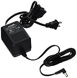
Unregulated Wall-Wart
An unregulated supply does not actively control its output voltage. The voltage it delivers is load-dependent – under light load it may output significantly more than its labeled voltage; under heavy load it sags. The BOSS ACA supply is a well-known example. Component voltage ratings and bias points must account for the higher end of the unregulated supply’s output range, not just its nominal value.
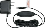
Regulated Wall-Wart
A regulated supply uses internal circuitry to maintain a stable output voltage regardless of load variation. The BOSS PSA-120S (9VDC, center-negative, regulated) is the standard that most modern pedal designs target. From a design perspective, a regulated supply gives you a predictable, stable voltage to build around. It is worth noting, however, that regulated does not mean noiseless. A regulated supply still has residual ripple and switching noise on its output rail. We’ll look into dealing with that later in this article when discussing the power supply circuit.
Daisy-Chain Adapter
A daisy-chain cable takes one supply output and splits it into multiple connections for multiple circuits, all sharing the same positive rail and the same ground. From a design standpoint, this means your circuit’s power rail is shared with every other circuit on the chain. Any noise generated by those other circuits (particularly digital ones) has a direct path to your power input. If you know your design will be used in this configuration, your power supply filter needs to be robust enough to reject whatever arrives on that shared rail.
Isolated Multi-Output Supply
Isolated supplies like the Strymon Zuma, Voodoo Lab Pedal Power, and similar units give each output its own electrically independent ground. From a circuit design perspective, this is the cleanest operating environment. There are no shared ground paths, and there’s zero cross-contamination between circuits. If your design is noise-sensitive, understanding why isolation matters helps you communicate the power requirements clearly to anyone building or using the circuit.
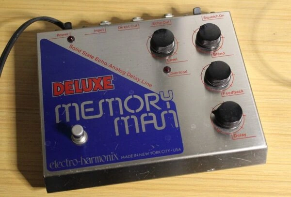
Mains-Powered Vintage Designs
Some vintage and high-power designs like the big-box EHX Deluxe Memory Man and the MXR Flanger 117 convert mains voltage to DC internally using a transformer, rectifier, and smoothing stage. Understanding this conversion process matters to a builder because it explains the origin of ripple voltage. The conversion process is covered in detail in the AC-to-DC section below, and the suppression of the ripple voltage will be addressed in the filter circuit later in this article.
⚠️ Mains Voltage Safety: 120VAC (North America) and 220VAC (Europe) are lethal voltages. If you are building, modifying, or servicing any mains-connected device, you must understand electrical safety practices thoroughly before working on it. This series does not cover high-voltage safety in depth. Treat any mains-connected circuit with the appropriate level of respect.
Polarity and Connector Standards
The vast majority of guitar effects circuits use a 2.1mm barrel connector for their DC power input. The connector has two contacts: the sleeve (outer ring) and the tip (center pin). Which contact carries ground and which carries the positive supply voltage defines the polarity of the connector. As the designer, this is a choice you make and document.
| Polarity | Center Pin (Tip) | Sleeve | Common Examples |
|---|---|---|---|
| Center-Negative (standard) | Ground (GND) | Positive (V+) | BOSS PSA, most modern pedals, virtually all standard pedalboard supplies |
| Center-Positive | Positive (V+) | Ground (GND) | BOSS ACA (vintage), some vintage EHX pedals, certain fuzzes |
Center-negative is the modern standard for guitar effects circuit design. When designing a new circuit, use center-negative unless you have a specific reason to deviate. More importantly: document the polarity in your schematic, on the PCB silkscreen, and on the enclosure. A polarity marking costs nothing and prevents a category of damage that reverse polarity protection diodes exist to guard against.
⚠️ Reverse Polarity Warning: Connecting a center-positive supply to a center-negative circuit applies reverse voltage to the entire design. Without reverse polarity protection, this can destroy semiconductors and other components immediately. This is precisely why the diode protection circuit from Circuit 4: Diode Protection is a standard inclusion in every pedal design. If your build will be powered externally, reverse polarity protection is not optional.
Voltage and Current
Voltage
9V is the standard operating voltage for the majority of guitar effects circuits. Some designs operate at 12V or 18V, typically because the active components require more supply headroom for the intended application, or because the design’s specifications call for a specific operating voltage. The governing principle for a designer is straightforward: design your circuit for the supply voltage it will actually receive.
Component voltage ratings, bias points, and power dissipation calculations must all be based on the actual supply voltage, not an assumed or ideal value. Running a circuit above the rated voltage of its components risks immediate or gradual failure. Running it below the design voltage may produce unpredictable behavior, as some circuits will not function correctly below a certain supply voltage threshold.
If your design requires a voltage that differs from the available supply (for example, a 5V rail for a digital component inside an otherwise 9V design) that is the use case for the linear voltage regulator covered in Circuit 9: The Linear Regulator. If your design needs a negative voltage rail, that is the use case for the charge pump covered in Circuit 10.
Current Draw
Current draw is the amount of current your circuit pulls from the supply, measured in milliamps (mA). Before building anything, you can estimate the expected current draw from component datasheets by summing the quiescent current (Iq) of each active component in the design. Every op amp, transistor, and digital IC datasheet specifies a quiescent or supply current rating. Add them up and you have a pre-build estimate. Then, once the circuit is built, you measure to verify. The measurement method is covered in the next section.
Always check the quiescent current specification in the datasheet of each active component in your design. The range varies significantly between component types:
| Circuit Type | Typical Current Draw | Notes |
|---|---|---|
| Simple analog (single op amp buffer, passive filter) | 1-10mA | Low draw, sum Iq from each op amp datasheet |
| Complex analog (multi-stage overdrive, compressor) | 10-25mA | Still a light load for most regulated supplies |
| Digital / DSP (delay lines, modulation engines) | 50-300mA | Verify with specific IC datasheet, varies widely |
| Complex digital (full DSP platform, FPGA) | 200-500mA+ | May require a dedicated supply output |
When a supply cannot deliver enough current, the supply voltage sags under load. That sag may manifests as noise: audible hum, buzzing, and instability in analog circuits, and unexpected resets, erratic behavior, or signal dropout in digital circuits. The circuit is not poorly designed; it is being starved of current. Understanding this before the build prevents a frustrating class of debugging problems after it.
Current budget: If your supply is rated at 500mA and the estimated total current draw of all circuits sharing that supply is 600mA, the supply cannot meet the demand. The rail voltage will sag and every circuit on the supply will be affected. Always leave current headroom in your power budget. Do not design to the rated maximum of the supply.
Measuring the Current Draw of Your Design
Once a circuit is built, measuring its actual current draw verifies your pre-build estimate and confirms the design is behaving as expected. There are two practical methods.
Method 1: Series Ammeter
The direct method is to insert a multimeter set to DC current (mA or A mode) in series with the positive supply rail (between the power supply’s positive output and the circuit’s power input). Current flows through the meter, and the reading is your actual draw.
Steps:
- Set the multimeter to DC current mode. Use a range that covers at least 500mA. Make sure the test lead is in the correct input jack, as most multimeters have a separate high-current input (often labeled A or 10A).
- Break the positive supply line. On a breadboard or PROTIS 1 development board, this is straightforward: disconnect the positive rail and insert the meter leads in the break. On a completed pedal, the cleanest approach is a modified barrel connector cable with the positive wire cut and terminated to two test points.
- Power on the circuit and read the current. The meter display shows the actual DC current draw.
- Measure under realistic operating conditions. Some circuits draw different current depending on state. A digital pedal may draw more when engaged than when bypassed. Measure with the circuit in its highest-draw state to capture the worst case.
Method 2: Ohm’s Law Proxy (Non-Invasive)
If your circuit includes the power supply filter from the next section (specifically the series resistor R1) you can measure current draw without breaking any connections, using Ohm’s Law and a voltmeter.
A voltage drop appears across R1 that is directly proportional to the current flowing through it. Measure that voltage drop with a multimeter set to DC volts, then calculate:
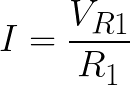
Example 1: R1 = 47Ω. You measure 47mV across R1. Then I = 0.047V / 47Ω = 0.001A = 1mA.
If you measure 470mV across R1: I = 0.470V / 47Ω = 10mA.
This method requires nothing more than probing either side of R1 with a standard voltmeter. No modification to the circuit or supply cable is needed. It is particularly useful for measuring current draw in a completed, enclosed pedal where breaking the supply line is inconvenient.
Which method to use:
Use the series ammeter method during development on the bench – it is direct, accurate, and easy on a breadboard or development board.
Use the Ohm’s Law proxy method for quick verification on a completed build where the filter resistor is accessible. Both methods give you the same information.
Daisy Chaining and Ground Loops
A daisy chain power cable connects multiple circuits to a single supply output, sharing the same positive rail and the same ground. Understanding what that shared ground means at the circuit level is directly relevant to how you design and specify the power requirements of your circuit.
How Ground Loops Form
When multiple circuits share a ground connection, any noise generated inside one circuit has a direct electrical path to every other circuit on the chain via that shared ground. This is called a ground loop, where noise circulates through the shared ground connections between designs and re-enters the audio signal path of each one.
Digital circuits are the worst offenders on a shared supply. Their internal switching regulators and clocked logic generate high-frequency noise that rides on the ground rail and contaminates the entire chain. Analog circuits are generally quieter contributors, but they are not immune to noise arriving on a shared ground from other circuits in the system.
The design implication is this: if your circuit will share a supply rail with other circuits, design your power input stage defensively. The power supply filter at the end of this article is your primary tool for rejecting rail noise that arrives at your power input from outside your own circuit. It needs to be present and correctly specified regardless of how clean the supply chain appears to be.
Why Isolated Supplies Eliminate the Problem
An isolated multi-output supply gives each output its own electrically independent ground. There is no shared ground connection between outputs. Noise generated in one circuit’s ground has no electrical path to another circuit’s ground. This is the cleanest operating environment for a noise-sensitive design.
⚠️ Mixed Polarity Warning: Center-negative and center-positive circuits cannot share a daisy chain cable. The polarities are opposite and connecting them on the same supply rail applies reverse voltage to one or more circuits in the chain. If a design requires both center-negative and center-positive supply connections, isolated outputs are the only safe solution.
How Mains-Powered Designs Convert AC to DC
This section applies specifically to designs that convert mains voltage internally, such as vintage pedals with a mains power cord, and the internals of some wall-wart power adapters. The process is the same in both cases, and understanding it as a builder clarifies why a DC supply might still have residual ripple on its output rail. That ripple is the primary target of the power supply filter circuit that follows.
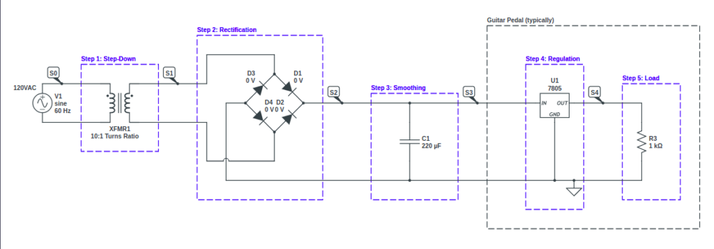
The conversion happens in up to four stages.
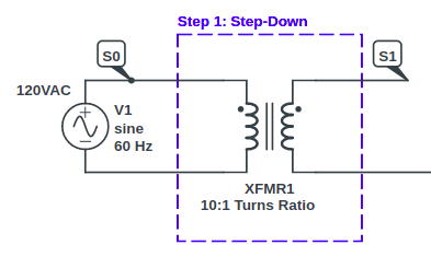
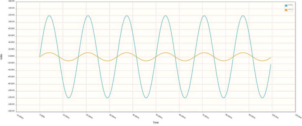
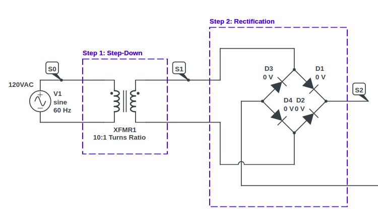
Step 1: Step-Down Transformer
Mains voltage (120VAC in North America, 220VAC in Europe) must be reduced before it is usable by guitar effects components. A step-down transformer handles this. Its turns ratio determines the reduction. For example, a 10:1 ratio steps 120VAC down to 12VAC on the secondary side. The output is still AC at this stage.
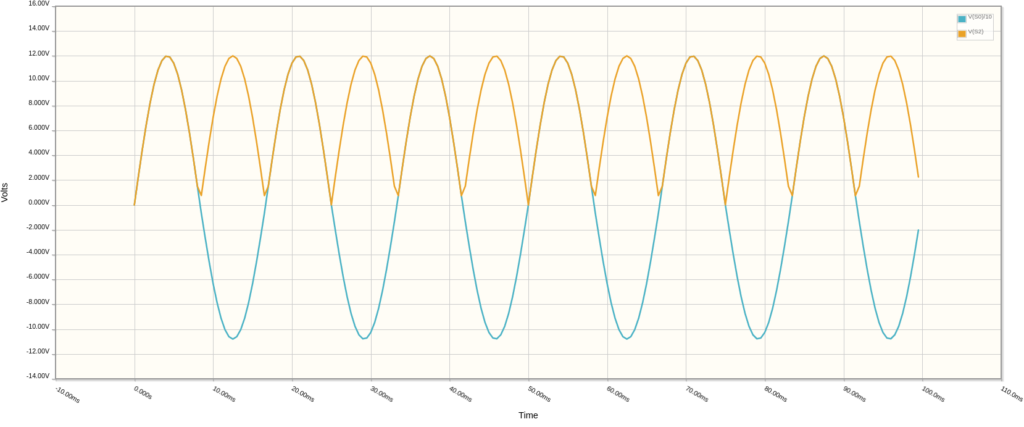
Step 2: Rectification
Rectification converts the AC signal into one that stays in positive territory. Two approaches exist:
- Half-wave rectification: A single diode removed the negative half of the AC waveform. Simple, but inefficient.
- Full-wave rectification: Four diodes in a bridge configuration flip the negative half into positive territory. Every half-cycle becomes positive. This is the standard approach.
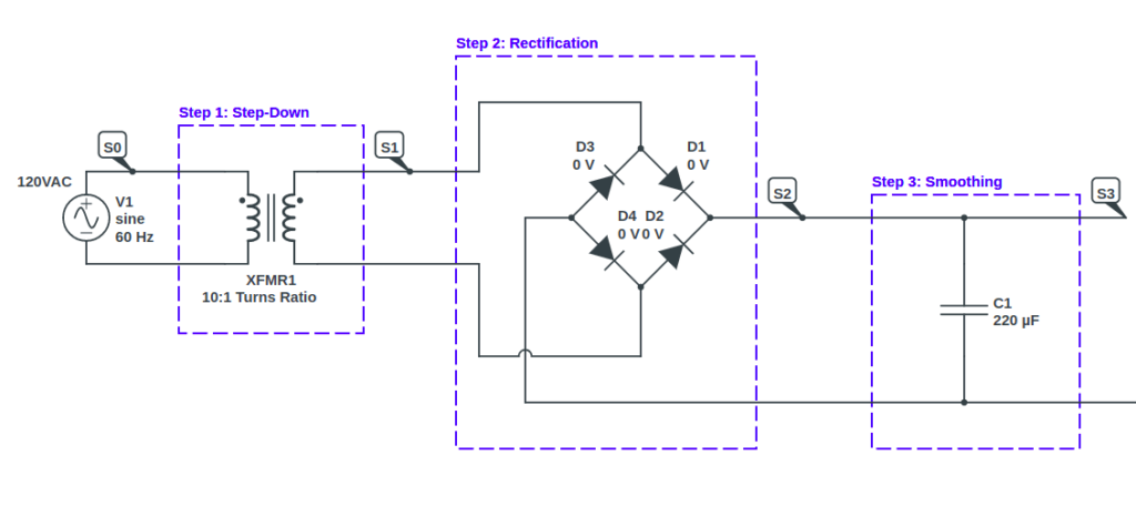
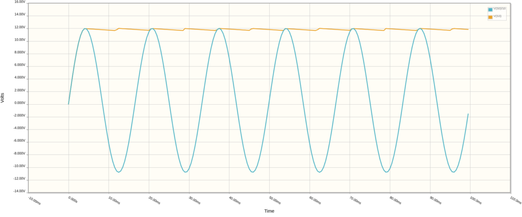
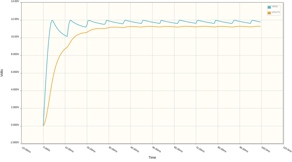
Step 3: Smoothing
The rectified signal pulses at twice the mains frequency. A smoothing capacitor across the output charges as the rectified voltage rises and discharges into the load as it dips, producing a near-constant DC voltage. What remains after smoothing is a small residual variation called ripple. In North America, the ripple is 120Hz (twice the 60Hz mains frequency) and 100Hz in Europe.
Ripple and 60-Cycle Hum
Ripple is the origin of 60-cycle hum (50-cycle in Europe). If ripple voltage reaches the audio circuit, it is amplified along with the audio signal and appears as a constant low-frequency hum at the output. This is true whether the ripple originates from a mains-powered design or arrives on the output of a wall-wart supply. Eliminating it before it reaches active components is one of the jobs of the filter in the next section.
Step 4: Regulation (Optional)
Some designs include a regulation stage to further stabilize the DC output voltage. Regulation is covered in Circuit 9: The Linear Regulator.
The Power Supply Filter Circuit
Even a regulated wall-wart could deliver DC with residual noise on the rail. There is ripple from the supply’s internal smoothing stage, RF noise from switching regulators inside modern supplies, and interference picked up by the cable between the supply and the circuit. Left unfiltered, all of that rides directly into the active components of your design.
The power supply filter is the last line of defense between the power input and your circuit’s active components. Using two complementary filtering stages, it addresses two distinct noise sources: low-frequency ripple and high-frequency RF injection. Some version of this belongs in every pedal design you build, regardless of how clean the incoming supply appears.
The power supply filter is built around the passive RC low-pass filter topology covered in Circuit 6: The Passive RC Filter. If the cutoff frequency formula or RC filter topology is unfamiliar, review Circuit 6 before continuing.
Version 1: R1, C1, and D1
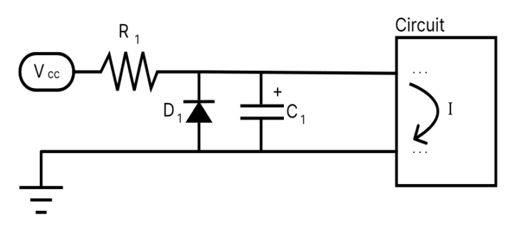
D1 is the reverse polarity diode from Circuit 4. R1 and C1 form the RC low-pass filter. The most important frequencies to filter out are in the 50-60Hz range, commonly found on mains power lines. Because of this, we want to make certain that we set our low-pass cut-off frequency to at most 50 Hz (shown in Equation 8.1 below).

Choosing R1: R1 should be as low as practical. Every ohm in R1 produces a voltage drop that takes reduces the available voltage to downstream components. 47Ω is the standard starting value, rated at 1/4W to ensure the power dissipation doesn’t cause any problems.
Solving for C1:
C = 1 / (2π × fc × R) = 1 / (2 × 3.14159 × 30 × 47) = 113 uF -> use 100uF (nearest standard)
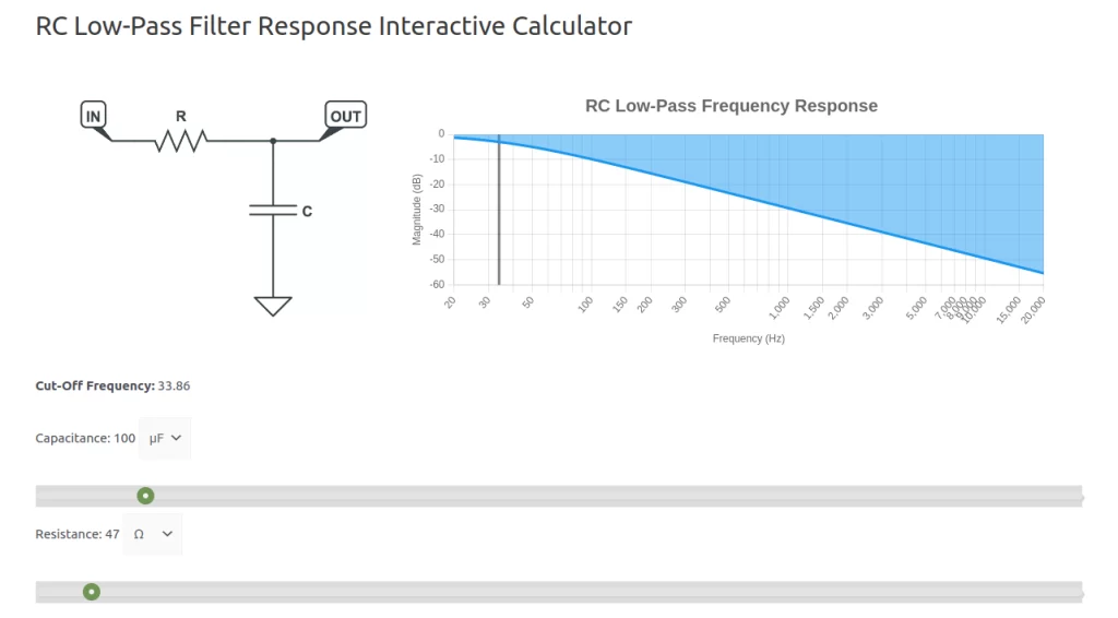
Verify the Actual Cutoff:
fc = 1 / (2π × R × C) = 1 / (2 × 3.14159 × 47 × 0.0001) = 33.9 Hz.
An actual cutoff of approximately 34Hz, which is well below the 50/60Hz mains interference target. C1 should be an electrolytic capacitor rated for at least the supply voltage plus margin (25V is a safe choice for a 9V design).
Dealing with RF Injection – Adding C2
R1 and C1 handle low-frequency ripple effectively. The second noise source (radio-frequency (RF) injection) requires a different approach. RF noise enters through the supply, the cable, and radiation from nearby electronics. Semiconductors can demodulate RF noise into audible interference in the audio band.
The issue is a capacitor property called Equivalent Series Inductance (ESL). At very high frequencies, ESL causes a large electrolytic capacitor to behave more like an inductor than a capacitor, losing its filtering effectiveness right in the frequency range where RF noise lives. The solution is a second, small-value capacitor in parallel with C1. Small film or ceramic capacitors have far lower ESL and maintain their filtering effectiveness well into the RF range.
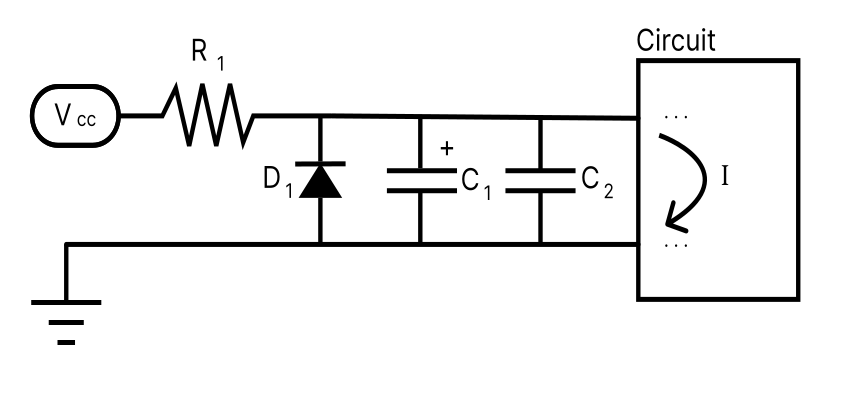
Choosing C2: 100nF (0.1µF) polyester or ceramic film capacitor.
The updated cutoff frequency with both capacitors in parallel (Equation 8.2, below):
fc = 1 / (2π × R1 × (C1 + C2)) = 1 / (2 × 3.14159 × 47 × (0.0001 + 0.0000001)) = 33.9 Hz

The cutoff frequency is essentially unchanged, as C2 at 100nF is negligible when combined with C1 at 100µF. What changes is RF suppression effectiveness, where C2 takes over as the dominant filtering element.
For further reading on ESL and its practical implications, see the Octopart Low-ESL Capacitor Guide.


Resources
[1] RC Low-Pass Filter Interactive Tool – Visualize the frequency response of any R/C combination.
[2] The Complete Low-ESL Capacitor Guide – Octopart – Background on capacitor ESL and its effect on high-frequency filtering.
[3] Circuit 4 of 48: Diode Protection – Reverse polarity protection (D1 in the filter circuit).
[4] Circuit 5 of 48: The Switched Jack – Battery connection and power switching.
[5] Circuit 6 of 48: The Passive RC Filter – RC low-pass filter topology and the fc formula used in this article.
[6] Circuit 9 of 48: The Linear Regulator – Voltage regulation for designs requiring a specific supply voltage.
Guitar Effects Design in 48 Circuits or Less
This post is part of the 48 Circuits or Less series by Stompbox Electronics. Each installment covers one fundamental pedal circuit building block – concept, demonstration, and supplemental resources.
View more articles in this series here.
Meet the Author:

Hi, I’m Dominic. By day, I’m an engineer. By night, I repair and modify guitar effects! Since 2017, I’ve been independently modifying and repairing guitar effects and audio equipment under Mimmotronics Effects in Western New York. After coming out with a series of guitar effects development boards, I decided the next step is to support that community through content on what I’ve learned through the years. Writing about electronics gives me great joy, particularly because I love seeing what others do with the knowledge they gain about guitar effects and audio circuits. Feel free to reach out using the contact form!
The Tools I Use
As a member of Amazon Associates, Stompbox Electronics earns and is supported by qualifying purchases.


