
Is your Line 6 DL-4 not working? Before you decide to scrap it or sell it for parts, consider this troubleshooting guide. We’ll look at common problems with the Line 6 DL-4 Delay Modeler pedal, as well as common solutions to those problems. Hopefully stepping through this process will get you closer to a working DL-4.

As a member of the Reverb Partner Program, eBay Partner Network, and as an Amazon Associate, StompboxElectronics earns from, and is supported by, qualifying purchases.
Disclaimer: Stompbox Electronics and/or the author of this article is/are not responsible for any mishaps that occur as a result of applying this content.
Preliminary Checks
Whether you’re an experienced technicians or not, there are some preliminary checks you should do before determining the need to follow this guide. Here is a short checklist on things to check:
Do you have the correct power supply for the DL-4?
The DL-4 states on the backside that it accepts a 9VAC power supply at 1200mA. This post on the Line 6 forum states that the original power supply – the PX-2G – was discontinued due to North American Level IV power efficiency regulations.
The recommended replacement – a Line 6 DCDL4TM – is a 12VDC center-positive supply at 1000mA. The Line 6 DL-4 (at least Revision 6) is designed to work with both power supplies.
Note also that the 9VAC power supply for the Digitech Whammy IV works with the Line 6 DL-4 as well. I’ve used it countless times.
Is the input jack plugged in?
The Line 6 DL-4 does not turn on unless there is a 1/4″ plug inserted into the input jack. Please make sure it’s there while troubleshooting the pedal.
Replacing Faulty Footswitches on the Line 6 DL-4
Each of the four switches on the DL-4 are tactile (similar to the one used in the Tubescreamer pedals). The wear and tear on those tactile switches is one of the most common causes of DL-4 failure. If you’re looking to replace them, the part number is TL1100DF260Q. They can be found on DigiKey or on eBay.
That said, there is a note posted in the DL-4 service manual regarding these switches. It states to “See Tech Bulletin 015 before ordering the part.” Unfortunately, us not being affiliated with Line 6, we don’t know what that means. To me it’s a red flag, so I would consider having the DL-4 modified with Soft-Touch switches if it comes to this point.
Getting the Line 6 DL-4 Schematic
There are five pedals in the Line 6 4X4 series: the DL-4, MM-4, FM-4, DM-4, and AM-4. This repair guide applies to all five versions, since all five use the same 4X4 circuit board.
The first thing you should do before you go deep into repairing a pedal is dig up its’ schematic. Here is the service manual for the Line 6 DL4, which includes the schematic and other relevant information. If it fails to download please contact me.
Troubleshooting the Power Section
If you believe the problem with your DL-4 lies in the power circuit, you can follow this section to troubleshoot it. This generally includes symptoms linked to the DL-4 not powering on.
All of the following measurements are made using pin 5 of U20 (the MAX660) as the ground reference. As for the oscilloscope waveforms, I’ve been using the Rigol 1102E oscilloscope for almost a decade. It’s perfect for basic troubleshooting, I whole-heartedly recommend it.

Step 1: Test the Input Power
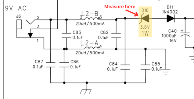
First we need to make sure there is power applied to the DL-4, which can be measured at the cathode end of the D16 zener diode. The waveform you measure will depend on the supply you’re using to power the DL-4 (see the previous section on Preliminary Checks). In this case, I was using a 9VAC supply.
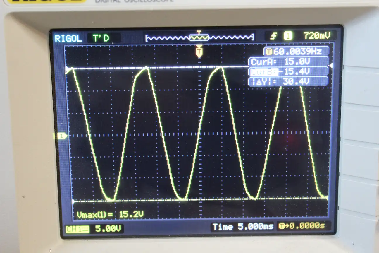
Remember, power supply voltages are given as an RMS value. Also, measurements are often slightly off compared to the stated output. In the photo above I measured a peak-to-peak voltage of 30.4V. Using this calculator, that equates to approximately 10.7Vrms which sounds about right.
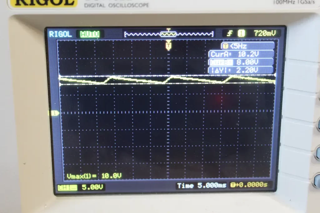
Step 2: Test the Filtered Input Power
The 1N4002 diode (D11) is used as a half-wave rectifier while capacitor C40 is used to smooth out the “humps”. The combination of the two results in a DC power waveform with a ripple of about 2.2V. The average voltage level measures to about 9Vdc, as seen in the oscilloscope trace below. The waveform was measured at pin 8 of the MAX887 (U14).
Step 3: Check the DC-DC Converter
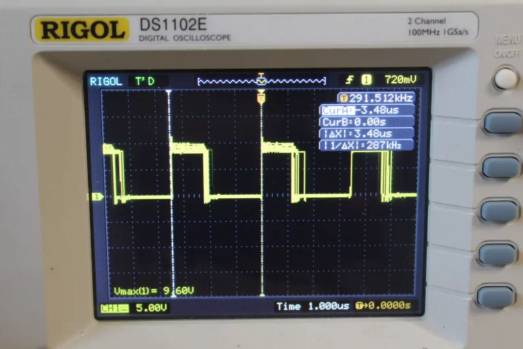
The Line 6 DL-4 uses the MAX887 as a DC-DC converter by taking the filtered 9V signal from step 2 and converting it to 3.3V with the help of some external components. The output waveform can be measured at pin 7 and looks like the trace on the oscilloscope screen below.
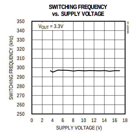
Notice the switching frequency is about 287kHz – right in-line with what the MAX887 datasheet says.
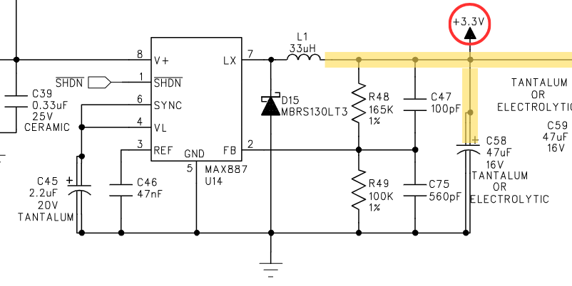
Step 4: Check the 3.3V Rail
After passing through the 33uF inductor you should read a steady 3.3VDC rail at the positive terminal of capacitor C58. This 3.3V power rail is responsible for powering most of the digital components on the DL-4. If your pedal is completely dead, then chances are you won’t find any signs of life at this stage in the power circuit.
Note that from this point on you can simply use a multimeter to measure the voltage levels.
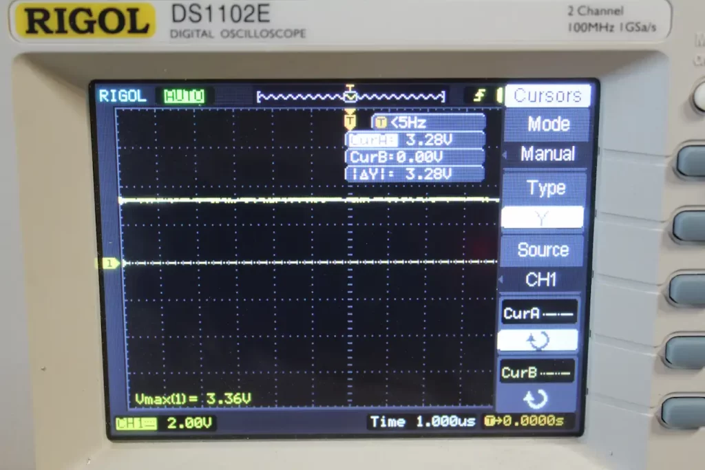
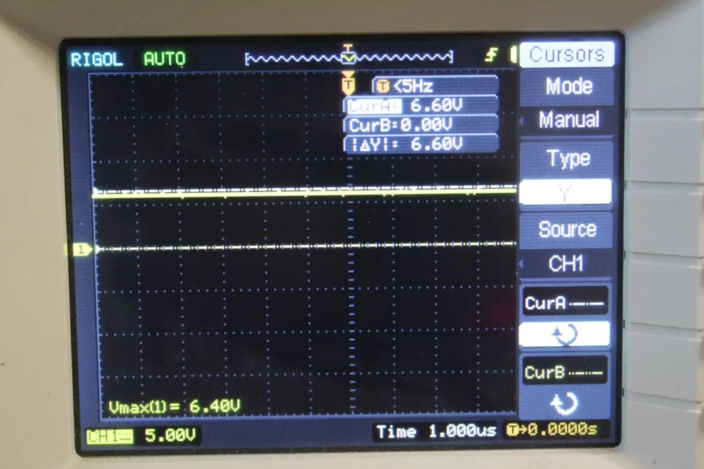
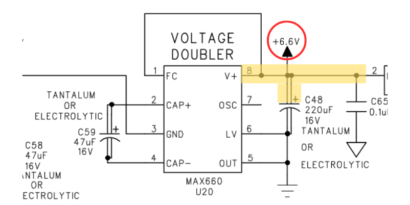
Step 5: Check the 6.6V Rail
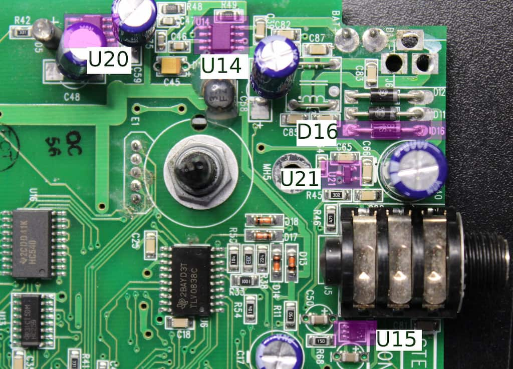
The DL-4 uses the MAX660 (U20) as a voltage doubler to boost the 3.3V rail to 6.6V. The input comes directly from the 3.3V rail and enters pin 3 of the MAX660. The output at pin 8 should read approximately 6.6V. You can also measure the 6.6V rail at the positive terminal of C48.
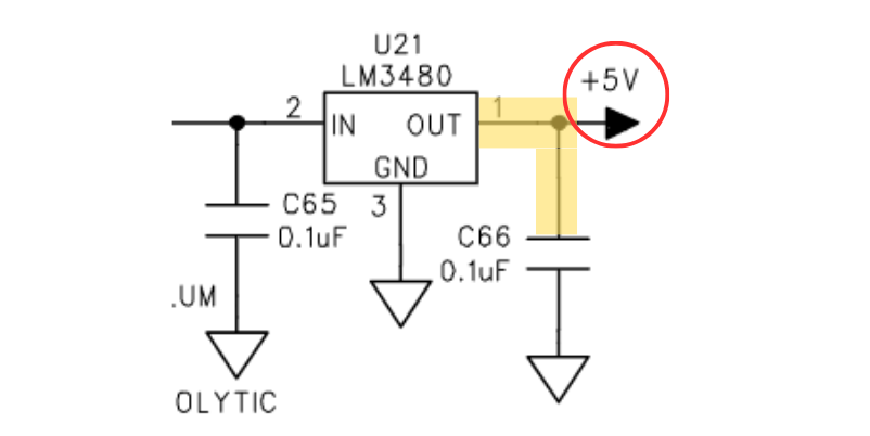
Step 6: Check the 5V Rail
Next up: the 5V rail. The 6.6V volts generated by U20 routes to the input of U21 – a tiny 5V voltage regulator near the expression pedal input jack. The chip is an LM3480IM3X-5.0/NOPB. You can measure the 5V output at C66. Specifically, the solder pad on the right side of C66.
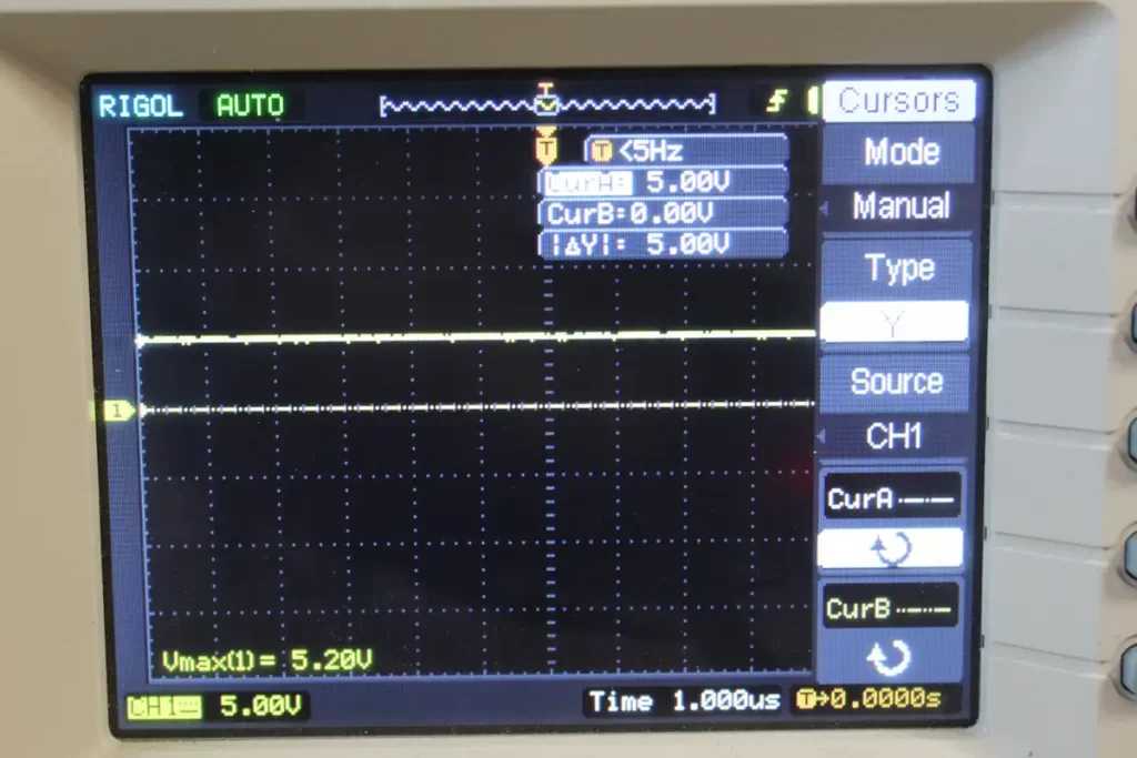
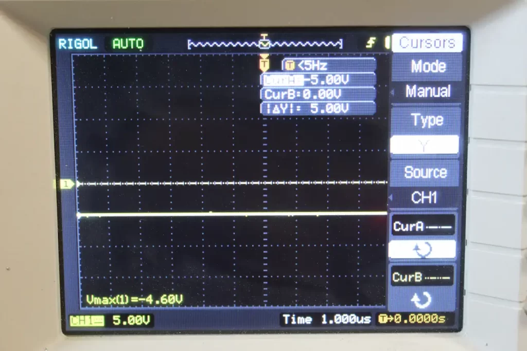
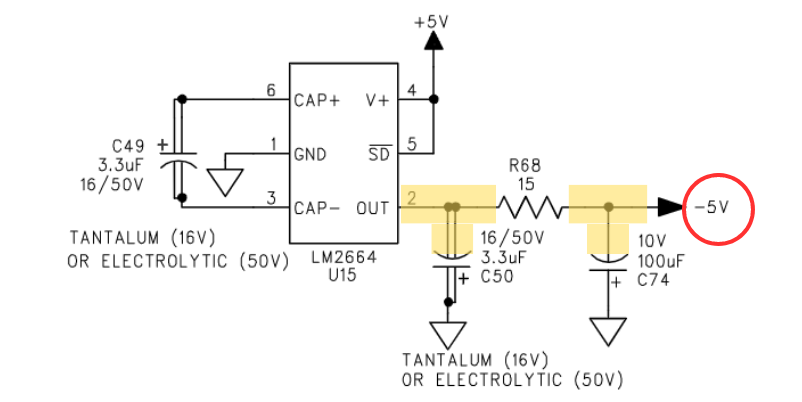
Step 7: Check the -5V Rail
Finally, to wrap up the power section, we need to make sure the negative 5V rail is OK. An LM2664M6/NOPB (U15) is responsible for converting the positive 5V rail to negative 5V. Line 6 used a small SOT-23-6 package, so it’s difficult measuring the output voltage at the chip itself. Instead, measure the negative 5V rail at the negative terminal of C50.
Additionally, you should measure the negative terminal of C74 for negative 5V. This will rule out any problems with the 15 ohm resistor (R68).
Checking the Digital Circuit for Signs of Life
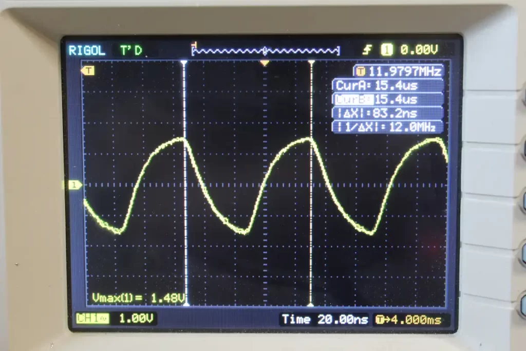
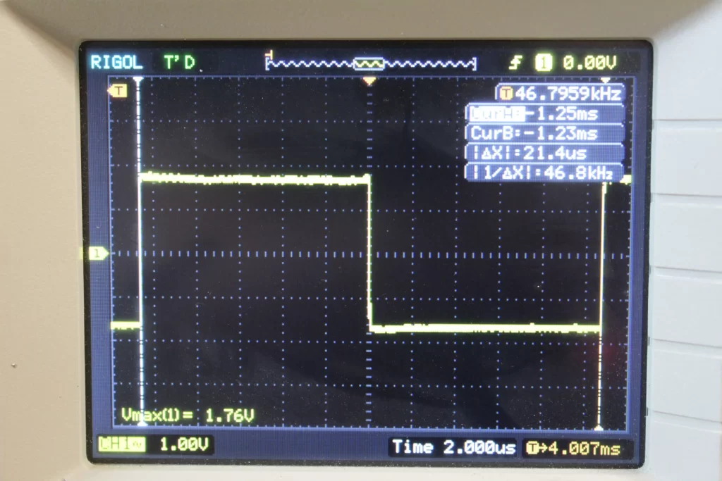
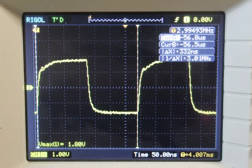
The DL-4 engineers provided a couple test points to check the clock signals associated with the digital circuitry. They are located in the center of the board and are labelled MCLK, LRCLK, and SCLK.
Measuring the waveform at MCLK should give you the master clock frequency at approximately 11.98 MHz. The LRCLK should read around 46.8kHz and the SCLK line should render about 2.9952MHz. These don’t have to read exact, but they should be very similar measurements.
Testing the Potentiometers
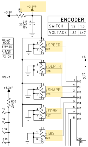
The pots used in the DL-4 aren’t the most robust, especially considering the plastic shafts. They could be a pain point, so it’s important to test these if certain controls aren’t working the way they should.
Each of the five potentiometers should cleanly sweep from 0V to a maximum of 3.3VDC. Using the circuit ground as reference, measure the voltage at the wiper terminal (lug 2) of each of the potentiometers. While measuring, turn the potentiometer from minimum to maximum, then back to minimum. Observe that the voltage rises from 0V up to 3.3V, then back to 0V.
Line 6 DL-4 Potentiometer Replacement
If there is a problem with one of the potentiometers you can purchase a replacement: the Bourns PTV09A-4025F-B102. This isn’t a direct part-for-part replacement, but it does have the correct footprint, taper, and shaft length.
Line 6 DL-4 Replacement Parts
Here’s a list of common Line 6 DL-4 replacement parts and links to where to buy them:
| Part Designation | Replacement Part |
|---|---|
| D16 | 3.6V 1W Zener Diode |
| D11, D12 | 1N4002 |
| D15 | MBRS130T3G or B1308-13-F |
| C40 | 1000uF 16V 10mm x 21mm (1) |
| C59, C48, C58 | 47uF 16V 8mm x 12mm (1) |
| C49, C50 | 3.3uF 50V 5mm x 12mm (1) |
| C74 | 3.3uF 50V 5mm x 12mm (1) |
| U14 | MAX887HESA+ |
| U15 | LM2664M6/NOPB |
| U20 | MAX660ESA+ |
| U21 | LM3480IM3X-5.0/NOPB |
| R24, R25, R26, R27, R28 | PTV09A-4025F-B102 |
| Footswitches | TL1100DF260Q |
Meet the Author:

Hi, I’m Dominic. By day, I’m an engineer. By night, I repair and modify guitar effects! Since 2017, I’ve been independently modifying and repairing guitar effects and audio equipment under Mimmotronics Effects in Western New York. After coming out with a series of guitar effects development boards, I decided the next step is to support that community through content on what I’ve learned through the years. Writing about electronics gives me great joy, particularly because I love seeing what others do with the knowledge they gain about guitar effects and audio circuits. Feel free to reach out using the contact form!
The Tools I Use
As a member of Amazon Associates, Stompbox Electronics earns and is supported by qualifying purchases.


