
The Line 6 DL-4 Delay Modeler has proven to be one of the most useful delays of its’ kind. The DL-4 was first introduced in 2000 as a convenient combination between digital and analog versions of delay in a single unit.
Today, we have a case of sudden death! This particular unit functioned perfectly in the past, but one fatal day the pedal started showing no signs of life. In this post I cover the process of how I repaired this DL-4.

As a member of the Reverb Partner Program, eBay Partner Network, and as an Amazon Associate, StompboxElectronics earns from, and is supported by, qualifying purchases.
Disclaimer: Stompbox Electronics and/or the author of this article is/are not responsible for any mishaps that occur as a result of applying this content.
Is your DL-4 experiencing issues? Do you have experience with electronics? Click here for my complete repair guide for the Line 6 DL-4.
Line 6 DL-4 Not Working: The First Step
If you have a Line 6 DL-4 that’s not working, the first thing you need to do is make sure you’re using the correct power supply. The DL-4 takes a 9VAC power supply with a 1200mA minimum rating. In a world of 9VDC pedals, it can be easy for someone to utilize the wrong power supply for this model.
Powering Your Line 6 DL-4
Line 6 recommends their PX-2 power supplies for the DL-4. If you are going the Voodoo Labs route, then the Pedal Power 2+ has inputs 5 & 6 dedicated for 9VAC pedals. Remember to set the corresponding DIP switch on the Pedal Power 2+ away from “NORMAL” position. The Voodoo Labs Pedal Power AC is also a good fit if you are running multiple AC pedals on your board.

Trying the DL-4’s Reset Procedure
Since the DL-4 schematic is near impossible to find I had to rely on existing blogs, forum posts, and my own intuition to solve this puzzle. The DL-4 has a reset procedure built into it, so I tried that first.
The DL-4 reset procedure is:
- Plug in a mono cable into the input jack.
- Hold down the two outside foot switches (Channel A and the Tap Tempo switch)
- While holding down those two switches, plug in the power connector (9VAC).
Holding those two buttons down for at least 5 seconds should show some sign of life. Unfortunately for me, this was not the case. Time to open ‘er up!
Disassembling the DL-4
Five (5) screws hold down the back plate of the DL-4. The circuit board itself is held down by four (4) other screws, plus a metal standoff in the center.
You also need to remove the knobs on the front in order to slide out the circuit board. There isn’t a perfect way to remove the knobs – I use a pair of pliers with a flat surface and firmly grip & pull them off. The trick is to make sure the pliers do not slide along the plastic, thus damaging it.
Next, you’ll have to remove the plastic nuts holding in the 1/4″ jacks on the top of the pedal. Once the screws, knobs, and nuts are removed you should be able to remove the circuit board easily.
Repairing the DL-4
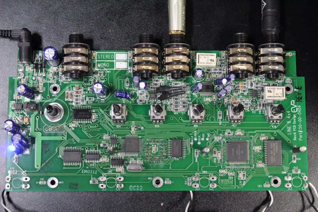
Looking towards the power conversion and regulating area of the back-side of the PCB, I noticed a decent amount of corrosion lining many of the solder pads. This was especially apparent around the power jack lugs. I removed the PCB from the unit, carefully removing the soft-touch foot switches along with it. It was a bit dusty, so I hit it with a round of compressed air as well.
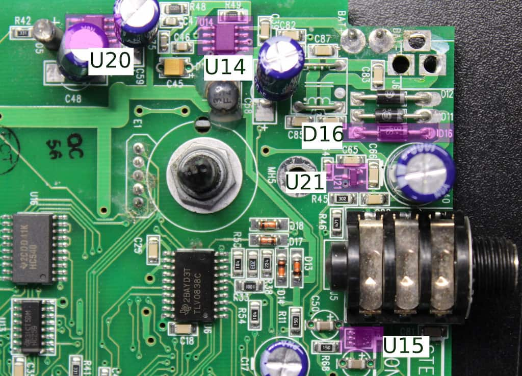
The Line 6 DL-4 Power Section
There’s great DIYstompboxes thread explaining how to test the power section of this circuit. Credit on this info also goes to the False Electronics’ article: Line 6 MM4 and DL4 Conversion.
The 9VAC power input first passes through a 3.6V Zener Diode (D16) and a 1N4002 diode. It then is buck regulated to 3.3V by a MAX887 converter (U14). The 3.3V feeds into a MAX660 Voltage Converter (U20) whose output should be 6.6V. This is then regulated to +5V by an LM3480 5V Voltage Regulator (U21). A -5V rail is produced from this +5V via an LM2664 Switched-Capacitor Voltage Converter (U15).
Testing the Power Section
With the PCB removed I could easily test the board with my meter. I plugged in the adapter and tested each power chip, but could not find any signs of life.
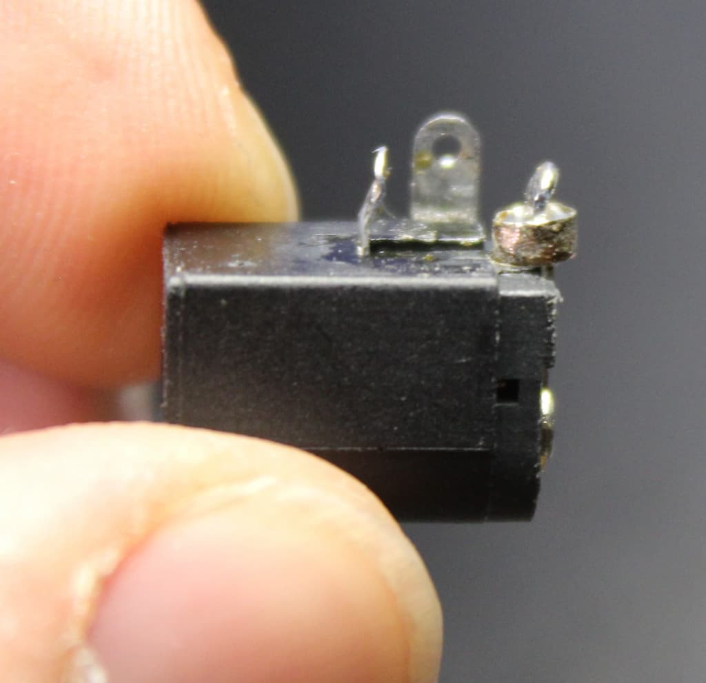
With none of the above showing any signs of power my immediate attention went to the power adapter jack. With the adapter plugged in I started checking the lugs of the adapter plug. When I pressed down on the power connector’s center-pin’s solder pad the pedal would briefly come back to life. I was able to recreate this a few times, so I zoomed in on the lugs of the power adapter.

I first applied fresh solder to each pad of the power connector. After cleaning with some alcohol, I plugged in the plug…nothing. I resorted to completely removing the power jack from the board, which gave me a chance to utilize the newest addition to the lab toolkit: the Hakko FR301 Desoldering Pump.
Removing the jack from the board also removed the tip connection’s copper via…the entire circumference of the via was corroded!
The Final Repair
I filed off the corrosion on the outer layer of the copper ring so that a solid solder connection could be re-established between itself and the board traces. The area was cleared of any excess solder, cleaned with alcohol, and prepped for a re-seating of the power jack.
Installing the power jack required some elevated attention to the solder flow onto the lug. It had to be heated a bit more than usual to more effectively disperse the heat throughout the re-installed via.
After cleaning with some more alcohol I plugged in the adapter and it came back to life.
Meet the Author:

Hi, I’m Dominic. By day, I’m an engineer. By night, I repair and modify guitar effects! Since 2017, I’ve been independently modifying and repairing guitar effects and audio equipment under Mimmotronics Effects in Western New York. After coming out with a series of guitar effects development boards, I decided the next step is to support that community through content on what I’ve learned through the years. Writing about electronics gives me great joy, particularly because I love seeing what others do with the knowledge they gain about guitar effects and audio circuits. Feel free to reach out using the contact form!
Spotlight
This fix was done for Buffalo-native band The Soft Love.
The Tools I Use
As a member of Amazon Associates, Stompbox Electronics earns and is supported by qualifying purchases.


