
Last Updated: January 20th, 2026

As a member of the Reverb Partner Program, eBay Partner Network, and as an Amazon Associate, StompboxElectronics earns from, and is supported by, qualifying purchases.
Disclaimer: Stompbox Electronics and/or the author of this article is/are not responsible for any mishaps that occur as a result of applying this content.
The Problem
The EHX Freeze is a fun little box used to sustain notes of a guitar. I’ve modified multitudes of Freeze pedals, probably every version there is. One particular design decision that EHX made during the life-cycle of the Freeze is to get rid of the metal lip around the power connector.
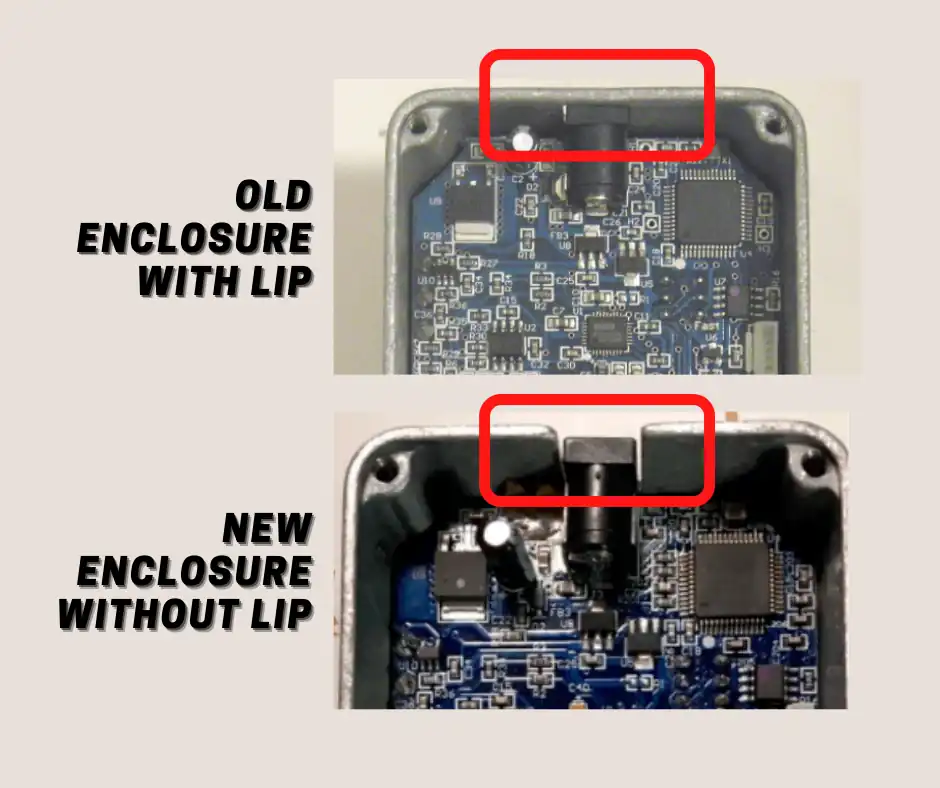
So what prompted EHX to make this change? Probably the amount of Freeze pedals they received with a broken mode switch.
That innocent piece of aluminum makes it next to impossible to remove the circuit board without doing damage to the toggle switch. For the untrained tech (and even trained techs!) there is a possibility of breaking the toggle switch in the process of removing the circuit board. All because of that metal lip! And the Freeze pedal in this repair was no exception to this long lineage of Freeze pedals with broken mode switches.
The EHX Freeze Mode Switch
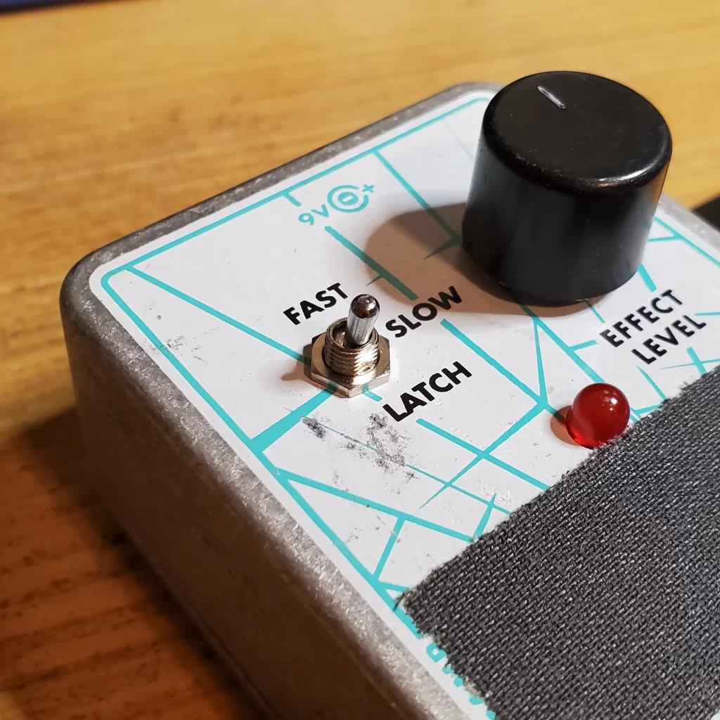
The toggle switch used in the EHX Freeze is a three-position toggle with an ON-ON-ON configuration. That means there isn’t a single position in which the common terminals are not connected to one of the lugs.
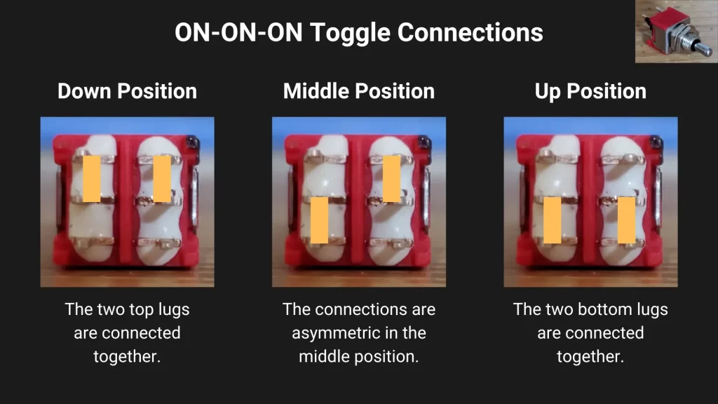
After testing a working Freeze pedal, I found that the switch should be installed so that the middle position matches the picture below.
Note that this configuration works for the Freeze version shown in the picture above (blue circuit board). I’m unaware of any design changes made by EHX to other versions of the Freeze where the placement of the switch may have changed.
Replacing the Mode Switch
About the Replacement Switch
The best replacement for the EHX Freeze mode switch is a Taiway 200-series sub-miniature toggle switch. The exact manufacturer part number is 200-MDP6-T2B1M2QE. The only place I’ve been able to find it is Love My Switches. Though, I had to make a few mechanical adjustments to the pins during installation. See Installing the New Switch below!
Removing the Switch
First, please be aware that removing this switch is not for beginners. If you have no experience with soldering or electronics, then please seek the help of a professional. There is real damage that can be done to the copper traces and components surrounding the switch.
Below are some of the tools I used to remove the switch (As an Amazon Associate, Stompbox Electronics earns and is supported by qualifying purchases):
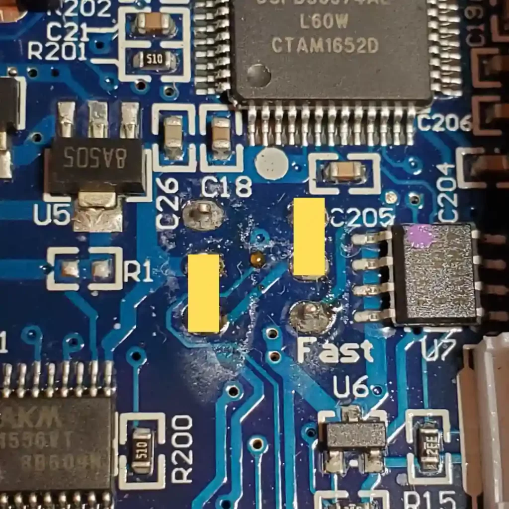
The first step is to apply new solder to the pads. This adds a layer of flux, which helps establish a consistent thermal profile. Second, use the soldering iron and desoldering braid to soak up the existing solder.
This should remove all the solder to the point where it’s fairly straight-forward to remove the switch. In cases where it doesn’t do the trick I usually use the hot air station to heat up the remaining solder and tweezers to remove the component while the solder stays melted.
Installing the New Switch
Before installing the new toggle switch, it helps to clean up the area with isopropyl alcohol.
Unfortunately, the pins on the toggle switch sold by Love My Switches are thicker than the PCB holes allow. By the end of the repair I had to get creative to make the switch work with the Freeze pedal.
The first thing I did was shorten the pins using a pair of wire cutters. Then, while I was soldering the part into the board, I used a higher temperature (around 750 C) and applied the solder so it could adhere to both sides of the board and the switch pins. Do not apply heat for more than 2 seconds at a time, as the higher temperature can start to melt the plastic casing if exposed to heat for too long of a duration.
Finally, I removed all the nuts/washers so the switch could fit between the enclosure and the circuit board with no spacing issues – leveling it with the height of the potentiometer’s circular body.
During the installation, I made sure to orient the switch in the position shown earlier in this post. Fortunately, the repair was successful and the Freeze is back to Freezin’.
Meet the Author:

Hi, I’m Dominic. By day, I’m an engineer. By night, I repair and modify guitar effects! Since 2017, I’ve been independently modifying and repairing guitar effects and audio equipment under Mimmotronics Effects in Western New York. After coming out with a series of guitar effects development boards, I decided the next step is to support that community through content on what I’ve learned through the years. Writing about electronics gives me great joy, particularly because I love seeing what others do with the knowledge they gain about guitar effects and audio circuits. Feel free to reach out using the contact form!
The Tools I Use
As a member of Amazon Associates, Stompbox Electronics earns and is supported by qualifying purchases.


