
In this post, you will learn the background of the external switch mod for the EHX Freeze pedal. Specifically we will focus on one of the most prominent users of the mod, Gilad Hekselman, and what led to the decision to go with a remote switch. Mimmotronics has decided to release the details of the modification, including what to look out for, later in the article.

As a member of the Reverb Partner Program, eBay Partner Network, and as an Amazon Associate, StompboxElectronics earns from, and is supported by, qualifying purchases.
Disclaimer: Stompbox Electronics and/or the author of this article is/are not responsible for any mishaps that occur as a result of applying this content.
Gilad Hekselman’s Use of the EHX Freeze
Gilad utilizes the EHX Freeze sound retainer in his modern jazz guitar technique, in which chords are retained and lead lines are played over it. It’s a pretty standard use of the Freeze, but it can be clumsy for first-time users of the pedal to master. Gilad seems to have developed his technique to make it seemless.
While I couldn’t pin-point exactly which songs the Freeze was used in (I could swear it can be heard in “Will You Let It?” on Trio Grande), there are video clips you can find on the net of his usage of the Freeze.

Find Trio Grande on Amazon
Jazzing with the EHX Freeze
The problem Gilad was having involved the Freeze footswitch being too loud for intimate performances. In order to better the experience, Gilad sought out modifications to make the Freeze more friendly to his listeners.
The first solution was to modify it with a Soft-Touch footswitch, as described in this video published in April 2016:
The Soft-Touch switch was still too loud, so another alternative was sought out. About 1 or 2 years later, Gilad contacted Mimmotronics to perform the Outsource Mod on his EHX Freeze.
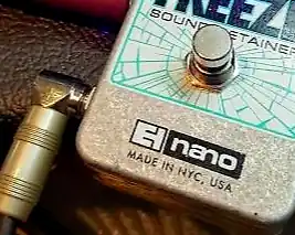
The Outsource Mod involves installing a 1/4″ jack to the Freeze so a remote footswitch can trigger the pedal. This ended up working out great, because a quiet keyboard sustain pedal can be used to trigger the Freeze instead of a standard guitar pedal footswitch.
In a Rig Rundown interview with Chris Kies from Premier Guitar (above) Gilad describes how the Outsource Mod made his experience using the Freeze more bearable. He prefered the keyboard sustain pedal for two reasons:
- It completely eliminates the sound of any click you could get from a standard guitar pedal footswtich. Keyboard sustain pedals are built with ease of use in mind, whereas guitar pedal footswitches simply don’t have that kind of intent behind their design.
- The form of the sustain pedal is compact and thin, making it easier to press when sitting or standing. This allows Gilad to be able to lightly press on pedal, whereas pressing a guitar pedal footswitch is a much less subtle movement.
The exact model Gilad used for triggering the Freeze through the Outsource mod is a Casio SP-3 Pad Sustain Pedal.
Modifying Your EHX Freeze
Stompbox Electronics’ Modification Service
You can have your Freeze modified the same way Gilad did through Stompbox Electronics’ modification services. Simply browse the Freeze mods page here and choose your desired Freeze mods.
How to Perform the External Switch Modification for the EHX Freeze
If you know a reputable technician in your area and would rather use the services of someone local, or if you would like to try the modification yourself, Stompbox Electronics has decided to release the information required to successfully install the Outsource modification. See below for details.
Step 1: Parts
First, you need to collect all the parts required for the external switch modification. There are a total of four (4) parts and some wires you will need to complete the mod, listed in the table below:
| Part | Qty | Description | Recommended |
|---|---|---|---|
| 1/4″ Guitar Jack | 1 | A standard 1/4″ guitar jack with the right form factor to fit in the Freeze Pedal. | Amazon |
| Soft-Touch Footswitch* | 1 | A Soft-Touch Footswitch, see 1.1 below. | Amazon |
| 681 Capacitor** | 1 | A 680pF film capacitor, see 1.2 below. | Amazon (kit) |
| 10k Resistor** | 1 | A 10k ohm resistor, see 1.2 below. | Amazon (kit) |
Step 1.1: Fitting a 1/4″ Jack (*)
Of course, some Freeze models make it difficult to install a 1/4″ jack. The stock footswitch that EHX uses gets in the way of where the new jack is installed. In this case, you need to replace the existing footswitch with a model that can be easily moved into a position where the new jack can fit.
The best model Soft-Touch footswitch I’ve found is the Short-Shaft Soft-Touch footswitch currently sold by LoveMySwitches.
Step 1.2: Alleviating Debounce Issues (**)
A momentary switch is expected to make and break contact just once. However, real momentary switches suffer from a condition called bounce: a spring-like action that occurs after the switch is pressed or released.
To alleviate bounce you can build an RC circuit, which “filters out” the effects of the bounce. See the schematic (later) for how to construct it.
Step 2: Remove the PCB from the Enclosure
Next, we need to remove the PCB from the Freeze enclosure.
- Unscrew the nuts for the stock footswitch and input/output jacks.
- Remove the Effect Level knob. It can be difficult to remove it using a screwdriver without making an indent in the plastic, so I recommend using a rocking motion to lift it a couple centimeters, then use your hand to pull and slide it off.
- Unscrew the other nut underneath the knob holding in the potentiometer shaft.
- Finally, there are 4 screws on the bottom of the enclosure holding in the back-plate. Remove the back plate and keep all the parts together for after you finish the modification.
Warning:
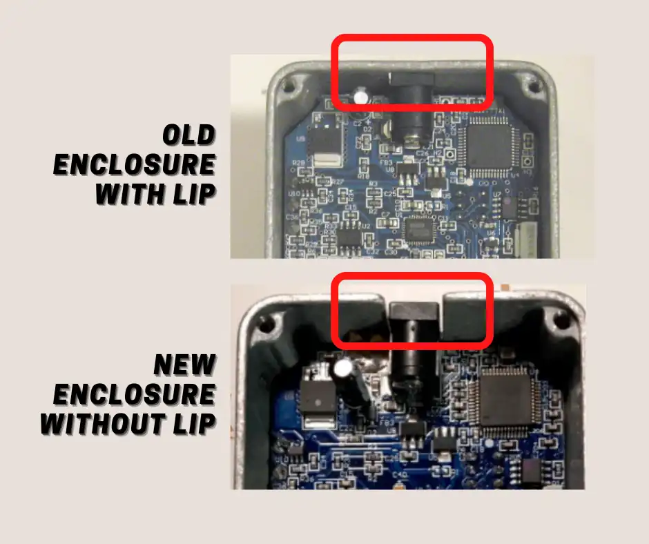
On early EHX Freeze models it is very difficult to remove the PCB without damaging the toggle switch!!
The aluminum enclosure has a lip underneath the power connector, requiring the use of two flat-head screwdrivers: one to “pry” the board out and the other to use as a sort of lever between the edge of the enclosure and the PCB.
The likelihood that you break the toggle switch is extremely high, so either be very careful or have someone experienced perform the modification.
Step 3: Drill the Hole for the External Switch Jack
The jack requires a 1/4″ diameter hole to be drilled into the enclosure for mounting. There is a lot of space on the output side of the enclosure. Be sure to drill near the bottom to make room for the footswitch.
You may need to use drill bit that’s a bit larger for clearance, but use the jack itself as a sizing guide to be sure. It is your responsibility to use proper safety measures and drilling techniques.
If you need help, I’ve written a post on getting started with drilling guitar pedal enclosure. Below, I’ve listed the relevant tools:
- 5-Speed Drill Press, Benchtop
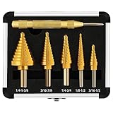
- Step Drill Bit Set & Automatic Center Punch- Unibit, Titanium Coated, Double Cutting Blades, High Speed Steel, Short Length Drill Bits Set of 5 pcs
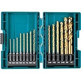
- 14 Pc. Titanium Drill Bit Set, 1/4 In. Hex Shank
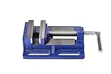
- Drill Press Vise 4″ – Light Duty
Step 4: Soldering the Components
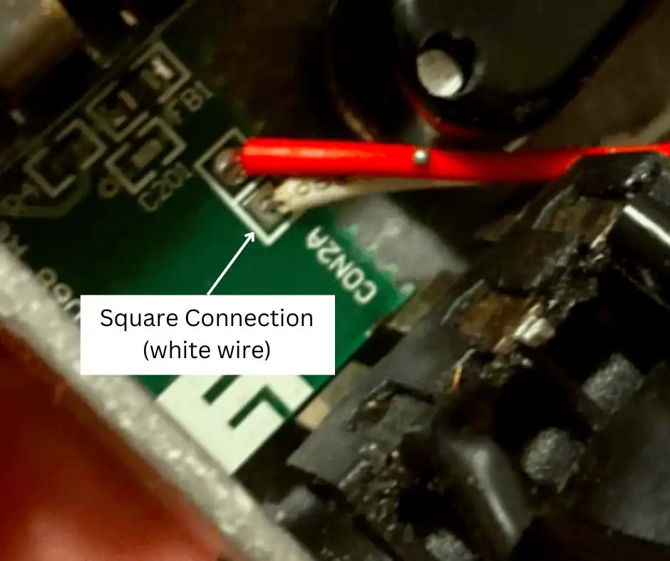
First, you need to find out which lug of the switch connects to ground. To do this, use a multimeter in continuity mode.
Place one probe on the sleeve connection of one of the stock jacks and test both lugs of the footswitch. Make a note of which lug is the one connected to ground.
Usually, the lug connected to the square via on the PCB is the grounded lug, but this is not confirmed on all models.
The following schematics show how to solder the external switch jack, as well as the new Soft-Touch Switch, if needed.
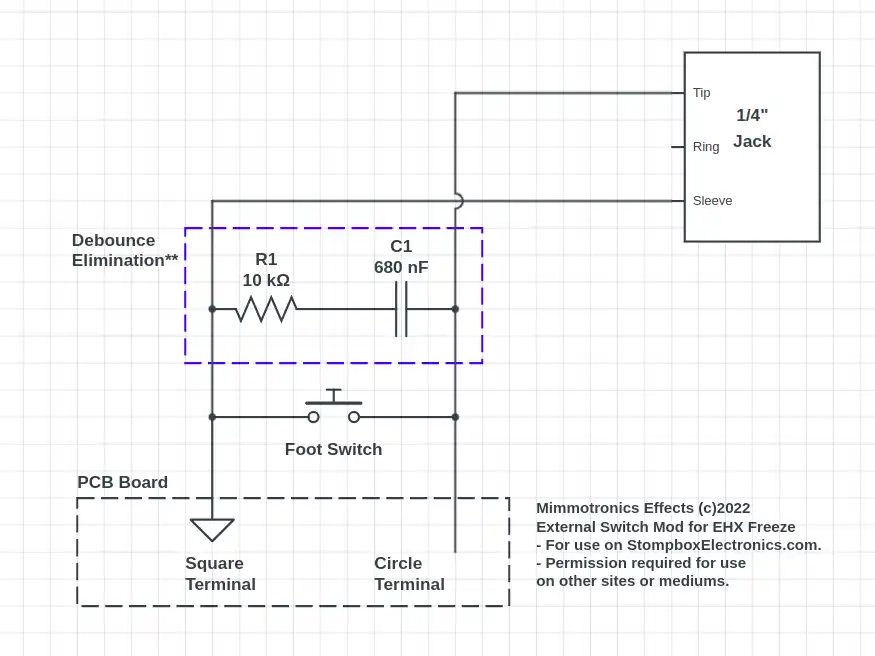
If you use the previously recommended 1/4″ jack where the sleeve connects to the enclosure, then you will only need to solder the wire connected to the tip. The sleeve connection must be connected to ground and, on the Freeze, the enclosure is already connected to ground through two metal rings around both input/output jacks, as well as through a metal piece next to the power connector.
Warning:
If you mix up which lug is connected to ground, then on power up the microcontroller will sense this and flash the LED at about a 0.5 second interval duty cycle. When you test the Freeze after the modification, and the LED starts to blink, just check your wiring and confirm that your ground connections are correct.
Step 5: Put It Back Together
Now that everything is soldered and the hole is drilled you are ready to mount everything back in the enclosure and test out the mod. First, I recommend reinstalling the PCB board, staying careful not to break the toggle switch. Screw in the input/output jacks on both sides to secure the PCB into place. Then, install the footswitch and, finally, the new 1/4″ jack.
Meet the Author:

Hi, I’m Dominic. By day, I’m an engineer. By night, I repair and modify guitar effects! Since 2017, I’ve been independently modifying and repairing guitar effects and audio equipment under Mimmotronics Effects in Western New York. After coming out with a series of guitar effects development boards, I decided the next step is to support that community through content on what I’ve learned through the years. Writing about electronics gives me great joy, particularly because I love seeing what others do with the knowledge they gain about guitar effects and audio circuits. Feel free to reach out using the contact form!
The Tools I Use
As a member of Amazon Associates, Stompbox Electronics earns and is supported by qualifying purchases.


