
On this Build Your Own, we cover what an Op Amp Boost is and how to breadboard the circuit. At the end, we cover how to use the Stompbox Electronics Op Amp Boost board for your own boosting needs!

What is an Op Amp Boost?
Boost circuits are relatively simple, they take in a signal, amplify it, and give you back the amplified signal. An op amp boost is a type of boost circuit that is built using an operational amplifier – or op amp.
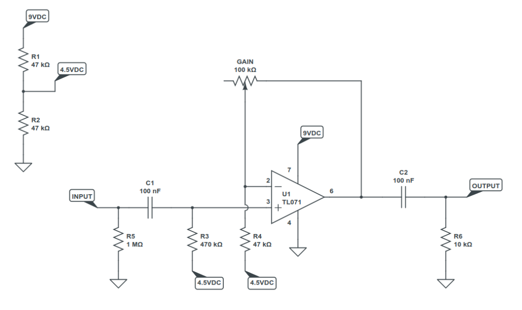
The circuit requires just an op amp and a handul of components. Here is the schematic for the op amp boost we’re going to be building in this post:
How to Breadboard an Op Amp Boost Circuit
In order to breadboard the boost circuit, you will need the components on the schematic above. Many options for assortment kits are available on Amazon, such as resistor kits and capacitor kits. I was surprised to see the TL071 available on Amazon as well. You can also find them on Tayda and Mouser if the import fees aren’t too much for your particular region.
| Component Designation | Component Value |
|---|---|
| R1 | 47k |
| R2 | 47k |
| R3 | 470k |
| R4 | 47k |
| R5 | 1M |
| R6 | 10k |
| GAIN | 100k (Linear) |
| C1 | 100nF (104) |
| C2 | 100nF (104) |
| U1 | TL071 |


Breadboarding Instructions
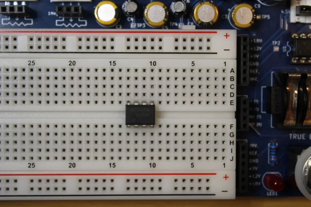
The photos below show the circuit being prototyped on a PROTIS 1 MINI development board for simplicity. It helps to quickly realize ideas and efficiently move a design from a schematic to prototype. Check out the PROTIS 1 development board for a larger prototyping space.
Please make sure that the PROTIS 1 MINI does not have power connected to it while breadboarding! Only apply power to test/troubleshoot breadboarded circuits.
Step 1
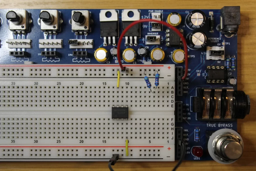
First, insert the op amp across the middle gap.
Step 2
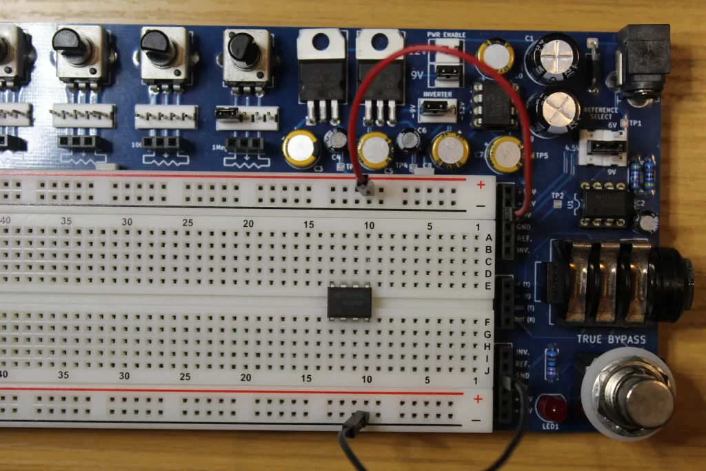
Second, assign which power rails to use for POWER (9V) and GROUND. For me, the top red rail carries 9V power. The black rails carry the 0V/GROUND.
Step 3
Then, build the voltage divider circuit responsible for generating the 4.5V reference voltage using resistors R1 and R2. Both resistors are listed as 47k in the parts list above, but anything in the tens of kilohms will be sufficient for this circuit.
Note that the PROTIS 1 MINI has a built-in reference voltage generator that you can use in place of resistors R1 and R2, saving some space. That said, I’ve used R1 and R2 here in case you’re following along using a normal breadboard.
Step 4
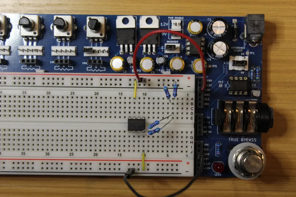
Now we can start connecting the power rails to the op amp. For breadboard-level wiring I use an assorted breadboard wires kit. Connect the 9V rail to pin 7. Connect the 0V rail to pin 4. (Shown in Step 5 with yellow jumper wires)
Step 5
Next, connect the reference voltage to pins 2 and 3. Use the 470k resistor (R3) to connect pin 3 and the reference voltage. Likewise, use R4 (47k) between pin 2 and the reference.
Step 6
Now that the reference voltage is connected to where it needs to be, we can focus on the input and output signals. Let’s do the input first!
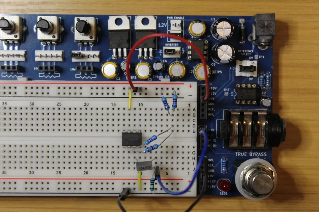
Connect capacitor C1 to pin 3 of the op amp. The other side of the cap gets connected to the input signal. Resistor R5 (1Meg) is there to “depop” the circuit when switching the footswitch ON and OFF. That goes between the input signal and ground.
The blue wire connects to the input signal from the 1/4″ jack on the MINI.
Step 7
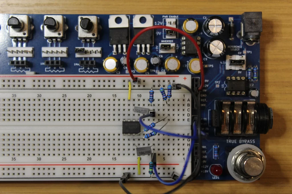
With the input signal wired up, let’s move onto the output signal. Capacitor C2 connects between pin 6 and the output. Resistor R6 (10k) serves a similar purpose to R5 – it depops the switch at the output side of the circuit.
Note that the two black rails for ground were connected during this step with a black wire.
Step 8
We’re almost done! Finally, connect the 100k potentiometer for gain control. The wiper of the pot connects to pin 2 of the op amp, while lug #1 of the pot connects to pin 6.
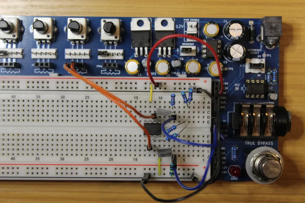
That’s it! Now plug in and play!
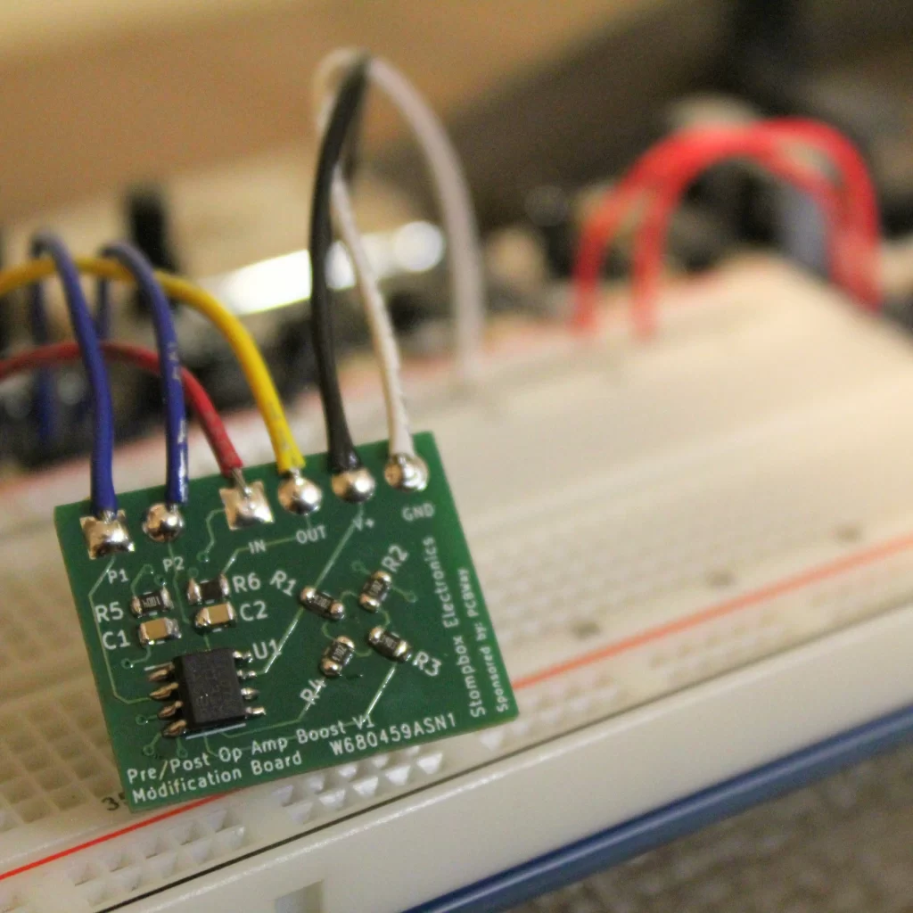
Building Your Own Op Amp Boost
If you’re interested in building your own op amp boost pedal, or if you need the circuit to add a boost to an existing pedal, then you can use the Stompbox Electronics Op Amp Boost Board. It’s an SMD version of the op amp boost circuit and was built using KiCAD and PCBWay.
If you’d rather build your own board, then you will need to learn two more skills to make the jump from breadboard to circuit board.
The first is getting familiar with an EDA tool. EDA stands for Electrical Design Automation – it’s a type of software that allows you to design printed circuit boards. I personally use KiCAD.
Second, you will need to get up to speed with printed circuit board fabrication houses (“fab houses” for short). For these boards, I used PCBWay. I found their platform relatively simple to use, their prices were reasonable, and the shipping was very quick. Within just a week or so from ordering I had the Op Amp Boost boards in-hand!

If you’re interested in having the Op Amp Boost board built by PCBWay:

Meet the Author:

Hi, I’m Dominic. By day, I’m an engineer. By night, I repair and modify guitar effects! Since 2017, I’ve been independently modifying and repairing guitar effects and audio equipment under Mimmotronics Effects in Western New York. After coming out with a series of guitar effects development boards, I decided the next step is to support that community through content on what I’ve learned through the years. Writing about electronics gives me great joy, particularly because I love seeing what others do with the knowledge they gain about guitar effects and audio circuits. Feel free to reach out using the contact form!
The Tools I Use
As a member of Amazon Associates, Stompbox Electronics earns and is supported by qualifying purchases.


