
Are you a musician looking to modify your EHX Freeze pedal for a unique and personalized sound? Understanding the circuit design of the pedal is essential for making modifications. In this article, we’ll take a deep dive into the different versions of the EHX Freeze pedal and break down their differences.
Whether you’re a seasoned gearhead or a curious musician, this article will provide valuable insights into the EHX Freeze pedal’s circuitry and how you can customize it to suit your needs.
Disclaimer: Stompbox Electronics and/or the author of this article is/are not responsible for any mishaps that occur as a result of applying this content.
History of the EHX Freeze
Having modified Freeze pedals for years, I’ve ran into various versions of the circuit. Out of necessity I had to take pictures, write notes, and document each version I came across so I knew, regardless of which version came into the shop, that I would be able to modify it.
Below I’ve organized each revision of the Freeze circuit board, mostly focusing on the circuit layout and the different processor and codec chips used in each version.
EHX Freeze EC-D68 Rev. B (Blue PCB)
EC-D68 Rev B is the earliest version Freeze I’ve come across.
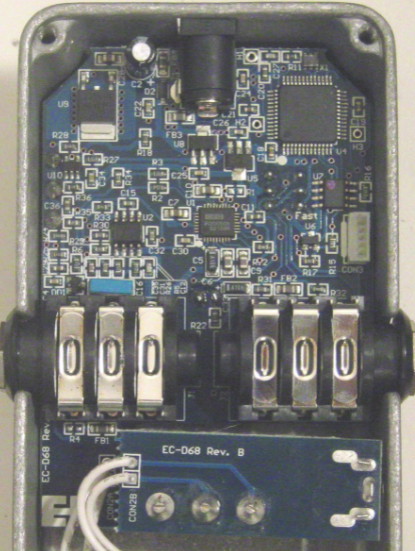
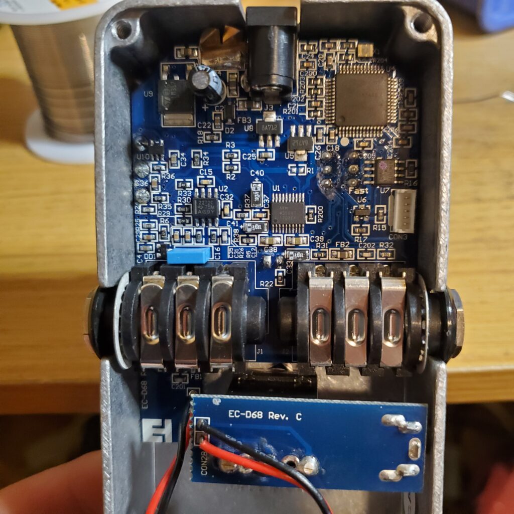
Revision B Mechanical Design
The circuit board is held in at 3 points: (1) the potentiometer, (2) the guitar jacks, and (3) the metal lip above the power connector.
There is only one point of contact for grounding the board to the metal enclosure – a mechanical spring that electrically connects the footswitch PCB to the enclosure, just underneath the output jack.
The momentary footswitches are loud in these early versions and take considerable pressure to activate. This can be a problem if you’re using the Freeze in more intimate settings. Luckily there’s a modification you can perform that swaps the loud, clunky switches with Soft-Touch switches.
Removing the Circuit Board from Early Version Freeze Pedals
To remove the circuit board from this version of the Freeze, you need to simultaneously pry it from the top of the enclosure while lifting it from underneath the power connector. This is extremely difficult to do without breaking the toggle switch or slipping and breaking off a surface mount component.
Because of the design in these early versions, many Freeze pedals end up in the junk bin. Luckily in later versions, as we’ll see, they started building enclosures without the metal lip around the power connector.
Revision B Electrical Components
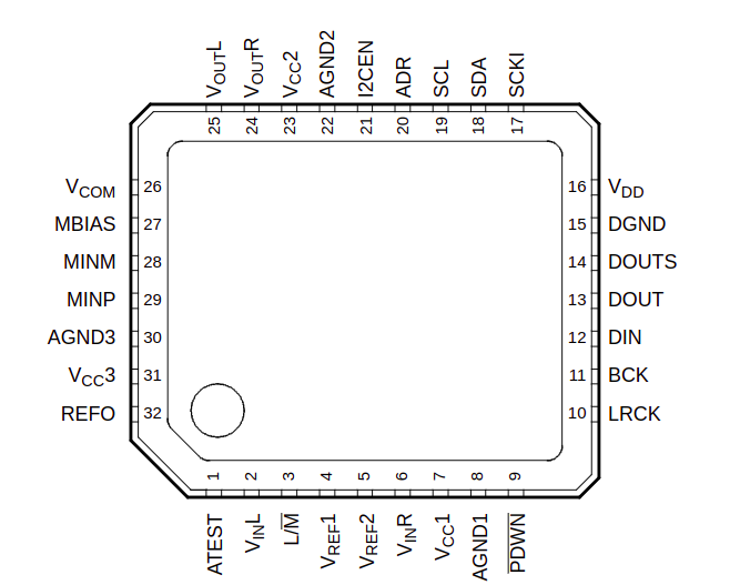
Most of the variation between Freeze versions occurs between which chips they used and the layout of the circuit board. The processor chip used in Revision B is the NXP Semiconductor DSP56374. The audio codec used is a Burr-Brown/Texas Instruments PCM3052A 24-bit stereo codec.
According to the datasheet the left/right inputs are fed in at pins 2 and 6, respectively. The left/right outputs are taken from pins 25 and 24. Only the right channel is used in Revision B, and the effect output is present at resistor R3.
EHX Freeze EC-D68 Rev. C (Green)
The next version would be EC-D68 revision C. The one pictured uses a green PCB, but there are other similar builds using a blue PCB board as well.
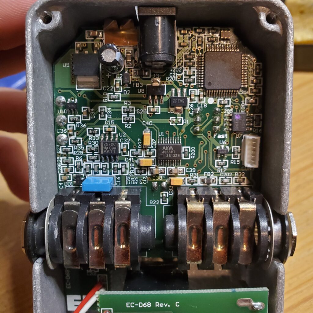
Revision C Mechanical Design
The circuit board is held in at 3 points: (1) the potentiometer, (2) the guitar jacks, and (3) the metal lip above the power connector.
There are also 3 points of contact that ground the board to the metal enclosure. The first is via a small sheet of copper at the top of the circuit board, sitting next to the power connector. The second is a spring that connects the footswitch’s circuit board to the metal enclosure, just under the output jack. The third ground point is via the metal rings around the input and output jacks, which only make contact with the enclosure when the backplate is on.
Revision C uses the same, if not similar, footswitches as Revision B, so the Soft-Touch Switch mod is still beneficial here.
Revision C Electrical Components
Most of the variation between Freeze versions occurs between which chips they used and the layout of the circuit board. The processor chip model is the same as Revision B – an NXP DSP56374. The audio codec used is an AK4556VT 24-bit delta-sigma audio, operating off of a power regulator in a SOT-223 package.
The input pins for the right and left channels are through pins 1 and 2, respectively. The right and left outputs can be accessed via pins 20 and 19, respectively. The only channel used in the Freeze is the Right channel, so the input signal is fed into pin 1 and the effect’s output signal leaves pin 20 and arrives at resistor R3.
EHX Freeze EC-D68 Rev. C (Blue)
There was one Revision C Freeze that ended up on my bench with a blue PCB. All the ground points were the same, and it used the same type of momentary switch. This is the earliest version I’ve seen where the metal lip above the power connector was removed, which helped immensely with removing the circuit board.
EHX Freeze EC-D68 Rev. J
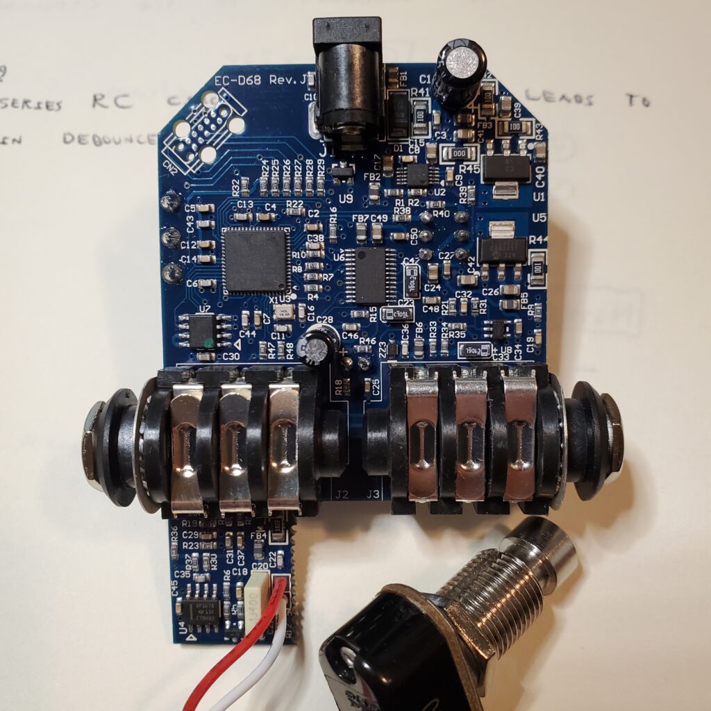
Revision J Mechanical Design
In Revision J, there is only one ground connection to the enclosure via the metal rings around the input/output jacks. By this revision EHX had been using quieter momentary switches – the ones without an audible click. That renders the typical Soft-Touch Switch mod less useful, with the only advantage being that it reduces the pressure needed to activate the pedal.
Revision J Electrical Components
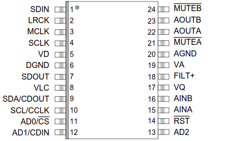
EHX changed out the processor for an Analog Devices Blackfin BF592KCPZ and the audio codec was swapped for a Cirrus Logic CS4270.
On the codec, the left/right input signals enter into pins 15 and 16. The left/right output signals come from pins 22 and 23. Revision J only uses the left channel (channel A in the datasheet) and the effect signal can be found at resistor _________________________________
Meet the Author:

Hi, I’m Dominic. By day, I’m an engineer. By night, I repair and modify guitar effects! Since 2017, I’ve been independently modifying and repairing guitar effects and audio equipment under Mimmotronics Effects in Western New York. After coming out with a series of guitar effects development boards, I decided the next step is to support that community through content on what I’ve learned through the years. Writing about electronics gives me great joy, particularly because I love seeing what others do with the knowledge they gain about guitar effects and audio circuits. Feel free to reach out using the contact form!
The Tools I Use
As a member of Amazon Associates, Stompbox Electronics earns and is supported by qualifying purchases.


