
In this article, we will explore how to fix the MXR Flanger volume drop issue by adding an op amp boost circuit. We’ll go through a brief overview of the non-inverting op amp circuit and provide some tips for integrating it into the MXR Flanger pedal.

As a member of the Reverb Partner Program, eBay Partner Network, and as an Amazon Associate, StompboxElectronics earns from, and is supported by, qualifying purchases.
Disclaimer: Stompbox Electronics and/or the author of this article is/are not responsible for any mishaps that occur as a result of applying this content.
The MXR Flanger Volume Drop Fix
The MXR Flanger 117 has been a go-to pedal for guitar players seeking the classic analog flange effect. However, some users have reported a frustrating problem with the pedal: when engaged, there is a significant drop in volume. Luckily, there’s a solution: we can add a boost circuit!
Preliminary Info
The Operational Amplifier (Op Amp)
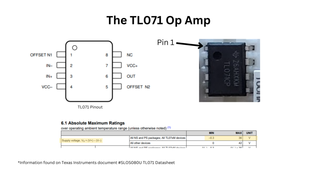
We’re going to build a non-inverting op amp circuit and add it to the pedal’s output. An op amp is an integrated circuit (also called a chip) that will allow us to amplify the output signal. We’re going to use the TL071, which can be purchased on Amazon or any online electronics distributors. Below is the pinout, the position of “pin 1”, and the absolute maximum supply voltage (36V) found in the Texas Instruments datasheet.

The Non-Inverting Amplifier Circuit
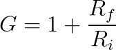
A non-inverting amplifier is a type of amplifier that doesn’t change the polarity of the input signal. In other words, the polarity of the output signal is the same as the input. It has predictable gain values, based on the values of the resistors you choose to build it. In particular – the ratio of the feedback resistor and the input resistor, plus 1.
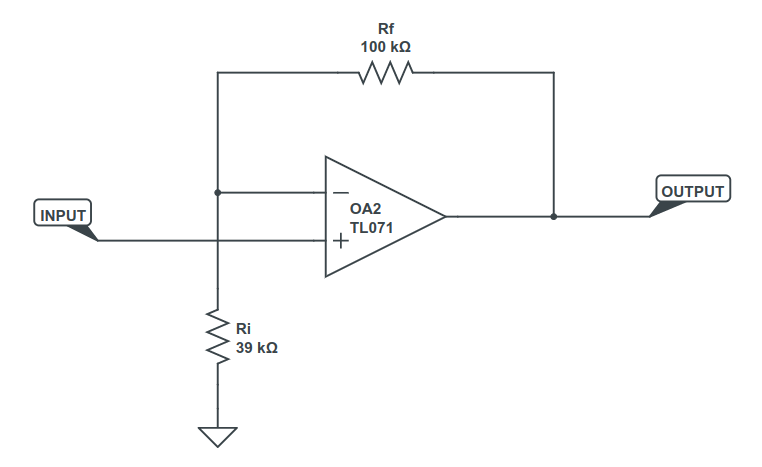
Below is an example of a non-inverting amplifier circuit, built using an op amp and only two resistors: Rf and Ri. Rf is the feedback resistor and Ri is the “input” resistor. The input signal is applied to the non-inverting input (+).
The feedback resistor is placed between the inverting input (-) and the output. The input resistor is placed between the inverting input and a reference voltage. In this case, the reference voltage is zero volts (or ground).
So, with the gain equation applied, the gain is 1 + (100k / 39k) = 3.56. That means the output signal is 3.56 times the size of the input signal. That is plenty for our MXR Flanger volume drop fix!
The MXR Flanger Circuit Board
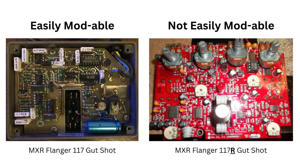
This modification is mainly concerned with the vintage MXR Flanger 117 circuit. To check whether your MXR Flanger can be modified, open up the back and see if there’s a RETICON SAD1024 chip. Additionally, check the image below. The correct circuit board is the “easily mod-able” one on the left.
If you have any other version (like the “117R” red PCB with surface-mount components) this article will not be so useful. But all hope isn’t lost! According to this video, the trimpot in the bottom left is allegedly responsible for Master Level control. Proceed with caution and comment below if that solves your issue!
Building the Op Amp Boost Circuit
The non-inverting amplifier circuit we introduced earlier is just an illustration, so we’re going to need to switch it up a bit to serve our needs. The first thing we’ll do is update the circuit to use a single-supply rail of 15V. After that, a variable resistance control will be added to allow us to adjust the gain.
Single-Supply Non-Inverting Amplifier
The phrase “15V single-supply power rail” is another way to say “all we have is +15V and ground.” Because there are no negative voltages involved, we’ll need to change the typical non-inverting op amp circuit to use a reference voltage. In this case, the reference voltage is 7.5V, which is half the power rail (15V / 2 = 7.5V).
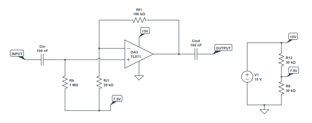
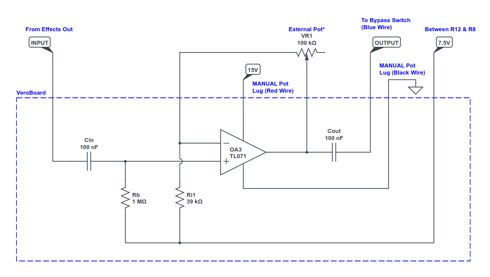
Here is the non-inverting amplifier adapted to a single-supply of 15V:

Capacitors Cin and Cout
The capacitors Cin and Cout are used to capacitively couple the input and output signals. The value of 100nF is pretty typical and the material used is poly film box. If you’re playing bass, you can increase the cap values to between 150nF – 220nF to let more bass into/out of the circuit.
The Power Circuit
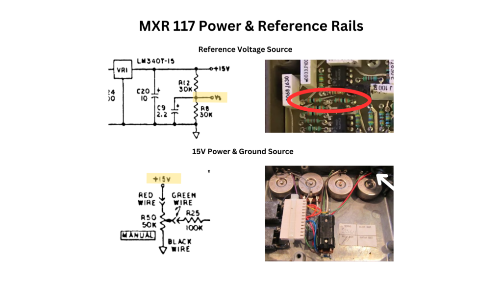
The power rail generates 15Vdc and the voltage divider produces a reference voltage of 7.5Vdc via the voltage divider formed by R12 and R8.
Rb, Ri1, and Rf1
The resistor Rb biases the input signal to 7.5Vdc so the input signal “swings” around a value other than 0V. The resistors Rf1 and Ri1 are the feedback and input resistors – the ones responsible for the gain.
Notice how the input resistor Ri1 connects to 7.5Vdc instead of ground. That is because the signal is being amplified and, since that signal rides on the 7.5Vdc level, we need to use that as a reference in the amplifier circuit.
Adding the Level Control
The MXR Flanger volume drop can be fixed using the circuit above, provided that the feedback and input resistors are chosen so the gain is exactly right for your taste. There’s only one problem: resistors come in specific values. It can be difficult to “dial-in” the right amount of gain to get the exact volume level you want by relying on a combination of standard resistor values.
To that end, let’s make the level adjustable by adding a variable resistor, VR1. See the modified circuit below:
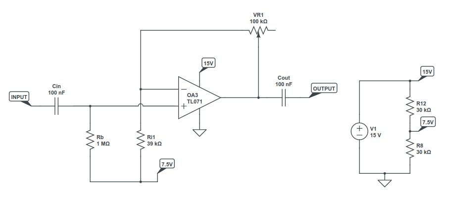
The feedback resistor was substituted for the variable resistor VR1. When the knob is all the way counter-clockwise, the resistance between the output and inverting pins is zero. From the gain equation, Rf goes to zero and the calculated gain becomes 1. That means the input is exactly the same as the output, which is the “stock” setting.
When the knob is turned all the way clockwise, the feedback resistance is 100k. The gain becomes about 3.56, just like before. So now we have a range of gain values, between 1 and 3.56, that we can adjust based on the position of a knob. Sweet!
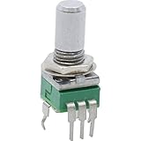
You can find the exact 9mm 100k potentiometer I used on Amazon.
Prototyping the MXR Flanger Volume Drop Mod
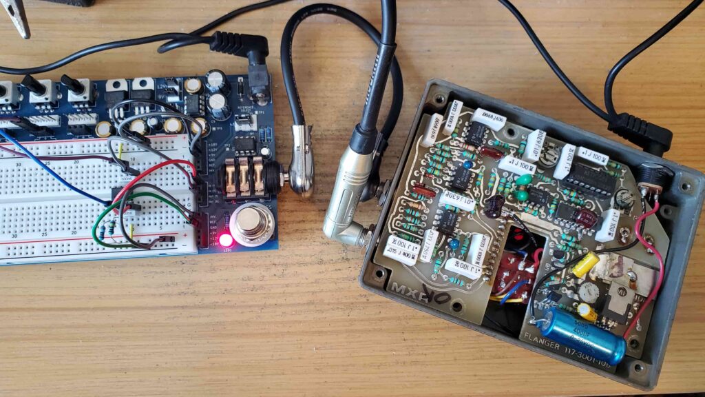
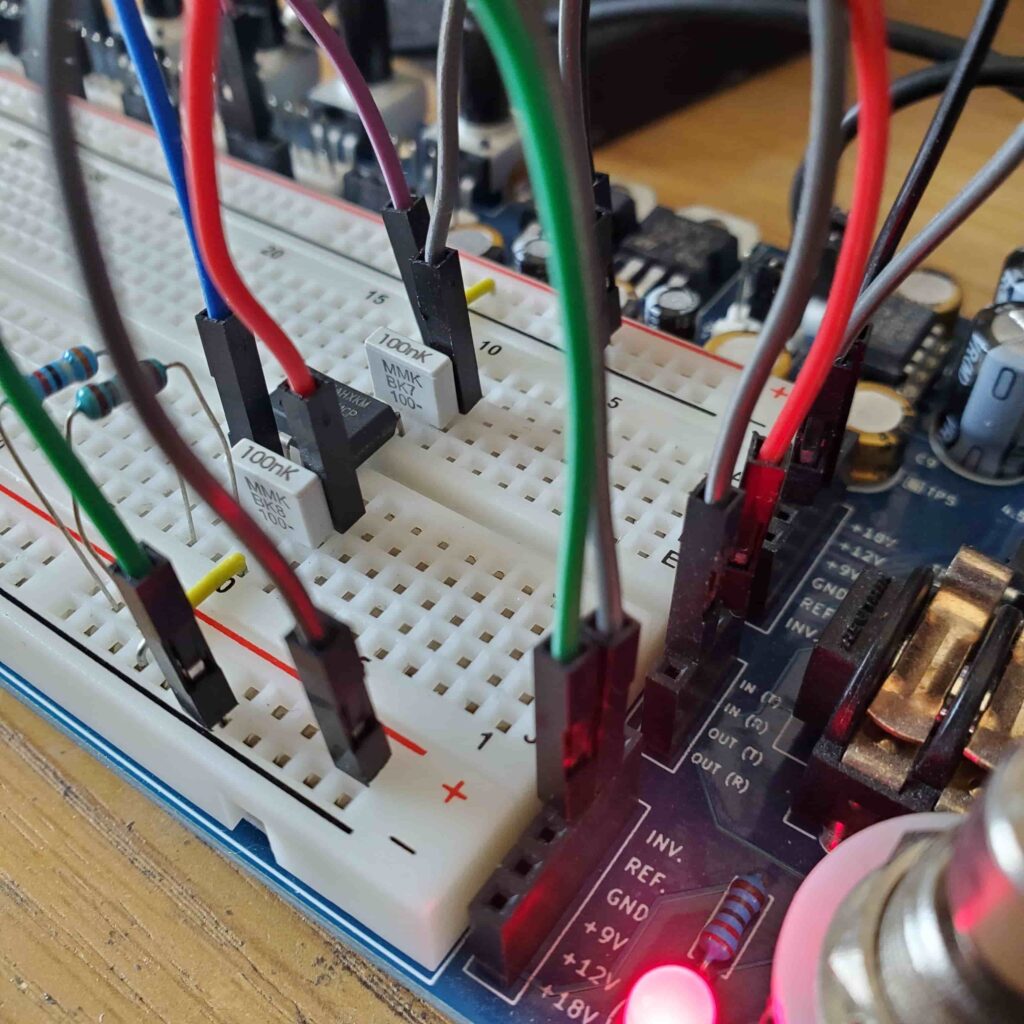
Before installing a modification it’s always a good idea to prototype the circuit first. Any breadboard will do – here I’m testing the boost circuit on a PROTIS 1 MINI.
Note that the MXR Flanger on the right is also modified with a true bypass switch, as well as for use with an 18Vdc power supply.
Installing the Op Amp Boost Circuit
To install the op amp boost circuit, take the following steps:
- Find the Reference and Power Rails
- Find the Input and Output Signals
- Build and Connect the Boost Circuit
- Install the Level Control (optional)
- Insulate and Place the Mod Board
1. Find the Reference and Power Rails
The reference voltage rail is generated by a voltage divider. Attach a wire to the node between R12 and R8 (both are 30k resistors) to access the reference voltage. For the 15V power rail, the red wire coming off of the Manual knob is +15V. You can heat up the lug with your soldering iron and tie into the 15V rail there. Likewise, the black wire coming from the Manual knob is the circuit’s ground.
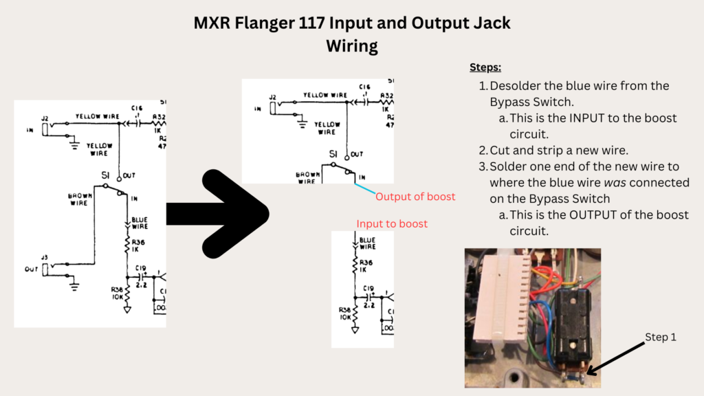
2. Find the Input and Output Signals
The boost is going to be put in the output path of the MXR Flanger. We need to be careful, though, that the boost is not in the bypass path – we only want to boost the effected signal, not the bypass.
3. Build and Connect the Boost Circuit
Next, we need to build the boost. You can choose to build it on a piece of veroboard, which can be found on Amazon.
4. Install the Level Control (optional)
If you can find a space for it, you can also install Level control. Since the MXR Flanger I was modifying was already modified for use with an 18Vdc supply, I was able to remove the transformer and use that space to mount a small 9mm 100k potentiometer for the Level control.

You could also take the “set-it-and-forget-it” approach and use a trimpot. With a trimpot you’ll have an internal control where you can set your desired level to a fixed value. Any time you want to change it, just open up the backplate and give it a tweak. By doing so, you’ll avoid having to drill any new holes for mounting components.
5. Insulate and Place the Modification Board
The last step is to insulate the modification board. You can use electrical tape for this – simply wrap the tape around the board to prevent any shorts from it moving around inside the pedal.
For placement, I like to put it underneath the bypass capacitor – just under where the MXR logo is printed.

Meet the Author:

Hi, I’m Dominic. By day, I’m an engineer. By night, I repair and modify guitar effects! Since 2017, I’ve been independently modifying and repairing guitar effects and audio equipment under Mimmotronics Effects in Western New York. After coming out with a series of guitar effects development boards, I decided the next step is to support that community through content on what I’ve learned through the years. Writing about electronics gives me great joy, particularly because I love seeing what others do with the knowledge they gain about guitar effects and audio circuits. Feel free to reach out using the contact form!
The Tools I Use
As a member of Amazon Associates, Stompbox Electronics earns and is supported by qualifying purchases.


