
By: Dominic Sciarrino | Stompbox Electronics | Last Updated: March 22nd, 2026
Almost every guitar effects pedal ever made has one thing in common: an indicator LED that tells you whether the effect is engaged or bypassed. The indicator LED circuit is one resistor and one LED: the simplest circuit in this series. But get the resistor value wrong and your LED is either eye-searingly bright or barely visible. This article covers everything you need to select the right components and wire the circuit correctly.
As a member of the Reverb Partner Program, eBay Partner Network, and as an Amazon Associate, StompboxElectronics earns from, and is supported by, qualifying purchases.
Disclaimer: Stompbox Electronics and/or the author of this article is/are not responsible for any mishaps that occur as a result of applying this content.
What is an LED?
LED stands for Light Emitting Diode. The word “diode” should be familiar: we saw how those work in Circuit #4: The Diode Protectors. Diodes allow current to travel in one direction only: from the anode (positive terminal) to the cathode (negative terminal).
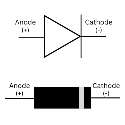
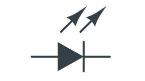
The schematic symbol for an LED is identical to a standard diode, with one or two arrows added to indicate light emission.
LED Physical Characteristics
When selecting an LED for a guitar pedal build, there are three physical characteristics to consider.
Lens Type: Clear vs. Diffused
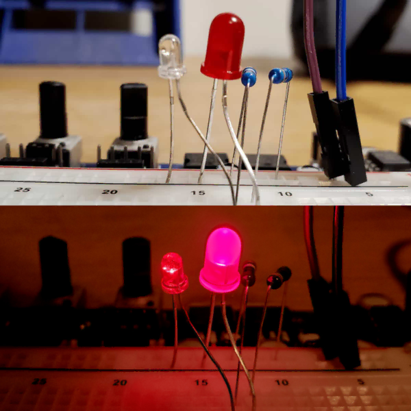
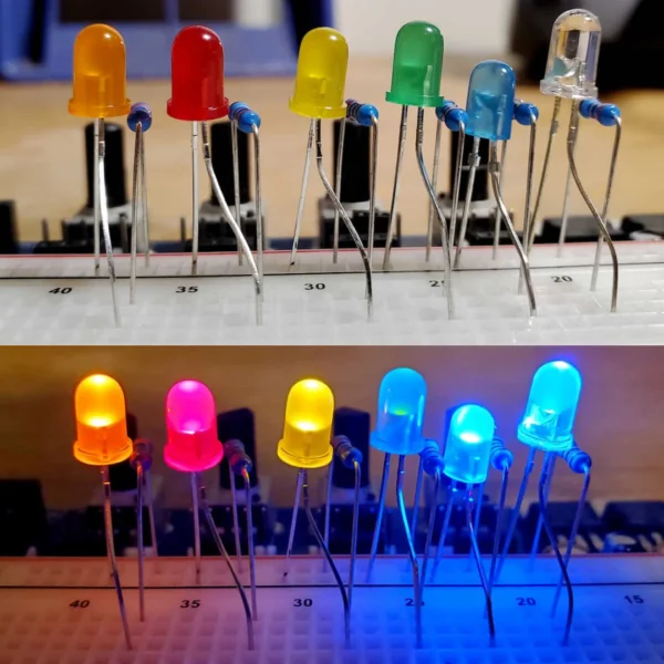
LEDs come with either a clear lens or a diffused lens. A clear lens concentrates the light into a tight, directional beam – bright straight-on bus less visible from the sides. A diffused lens scatters the light more evenly, giving a more uniform glow visible from multiple angles. For panel-mounted indicators behind a bezel, diffused is generally the better choice for visibility.
LED Color
The color of an LED is determined by the semiconductor material used to build the diode junction (not by the color of the lens itself). The most common indicator colors for guitar pedal builds are red, orange, yellow, green, blue, and white.
Mounting Style: Through-Hole vs. Surface-Mount
LEDs are available in through-hole and surface-mount (SMD) packages. For DIY guitar pedal builds, through-hole LEDs are the standard. The two most common through-hole sizes are 5mm and 3mm, which refers to the lens diameter. 5mm is the default for most standard builds. 3mm is used in tighter enclosures or where a smaller bezel is required. Electrically, both behave identically.
When mounting 3mm or 5mm LEDs, an LED adapter board can used/built for wiring.
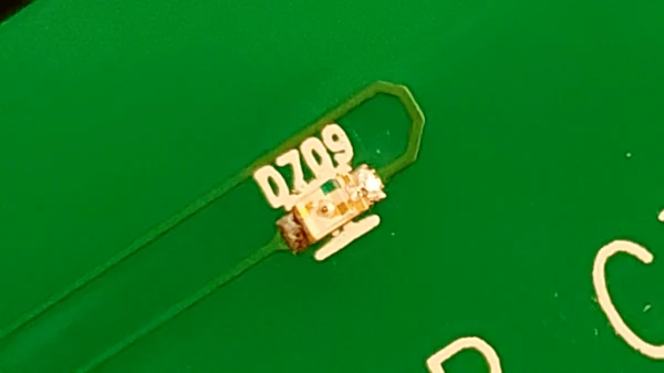
Surface-Mount LEDs appear in compact commercial designs and some mini pedals. They require soldering with tweezers and are less common in DIY builds.

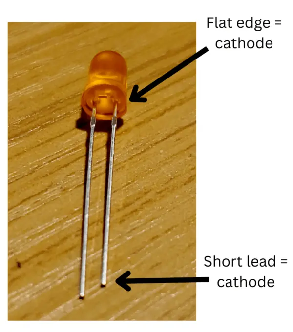
LED Polarity
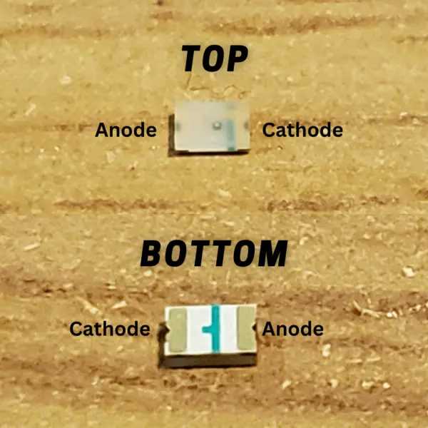
There are a few ways to tell which leads are positive or negative, depending on the type of LED. The negative side of a through-hole LED is marked with a flat edge and is the shortest of the two leads.
Surface-Mount LEDs are much smaller and compact, so it can be difficult to distinguish certain features. For surface-mount LEDs, the negative end is usually marked with a notch or dot. For models with clear packaging, a short green line marks the negative end.
⚠️Reversed LED: A backwards LED simply will not light. At 9V it will not be damaged, but it also won’t give you any indication that the circuit is working correctly. Always check polarity before troubleshooting anything else.
Electrical Characteristics of LEDs
There are four electrical properties that matter for indicator LED circuit design.
Forward Voltage (Vf)
The forward voltage is the voltage that appears across the LED terminals when current is flowing through it in the forward direction. This value depends on the semiconductor material, which means it varies by color. Red LEDs have the lowest forward voltage; blue, green, and white LEDs have higher values.
The table below lists typical forward voltage values by color. These are approximate – actual values vary by manufacturer and should be verified with the LED’s datasheet or measured with a multimeter in diode mode.
| LED Color | Forward Voltage (V) |
|---|---|
| Red LED | 1.8V |
| Yellow LED | 2.2V |
| Green LED | 3.5V |
| Orange LED | 2.0V |
| Blue LED | 3.6V |
| Violet LED | 3.3V |
| White | 3.0 – 3.6V (varies) |
Reverse Voltage (Vr)
The reverse voltage is the maximum voltage an LED can withstand when connected in reverse polarity. Exceeding the rated reverse voltage can destroy the LED. At 9V with a standard indicator LED, a reversed connection is generally safe, but do not rely on this. Always check polarity before applying power.
Forward Current (If)
The forward current is the current flowing through the LED from anode to cathode. Too much forward current causes the LED to overheat and burn out. This is the parameter we control by selecting a current limiting resistor (CLR). Never connect an LED directly across a power supply without a CLR.
Luminous Intensity
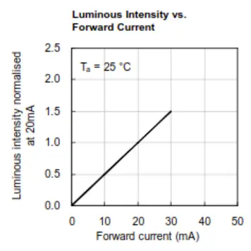
Luminous intensity describes how bright the LED will appear at a given forward current. Most LED datasheets include a Luminous Intensity vs. Forward Current chart that lets you determine the relative brightness at any operating point.
The Kingbright WP7113SRD/E red LED used in this article normalizes its luminous intensity to 20mA (meaning 20mA is the manufacturer’s reference brightness point).
Figure 7.9 below shows an example of such a chart from the datasheet. It’s saying that if you apply half the forward current to the LED, then the luminous intensity will be halved (0.5), meaning its proportional to the forward current flowing through the LED.
Single-Color, Bicolor, and RGB LEDs
Single-Color LEDs
Single-color through-hole LEDs are the standard for guitar pedal indicator circuits. They have one color and two leads. This is the component that this article primarily focuses on.
Bicolor LEDs
A bicolor LED contains two LED junctions in a single package, wired so that each junction conducts depending on the polarity of the applied voltage. The most common color combination is red and green.
Bicolor LEDs come in two internal configurations:
- Two-lead (anti-parallel): The two junctions are wired in opposite directions within the same package. Apply voltage one way and it glows one color; reverse the polarity and it glows the other.
- Three-lead (common-cathode or common-anode): Each junction has its own independent lead, plus a shared common. This allows both colors to be controlled independently and even mixed (to produce from red + green, for example)
RGB LEDs
RGD LEDs contain three junctions (red, green, and blue) in a single package, typically with four leads – one per color plus a common terminal.
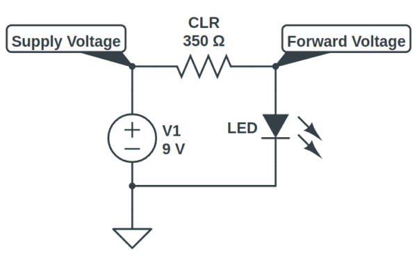
Designing the LED Indicator Circuit
The indicator LED circuit requires just two components: the LED and a current limiting resistor (CLR). The CLR prevents the LED from drawing unlimited current and burning out.
For a 9V pedal, CLR values between 1kΩ and 4.7kΩ cover most practical use cases. If you just want a working indicator without precision brightness tuning, a 2.2kΩ resistor is a reliable default for a standard red or orange LED at 9V.
To design for a specific brightness level, follow these four steps.
Step 1: Determine the Supply Voltage
Use the voltage powering the rest of the pedal circuit. For most DIY builds that is 9V. Some pedals run at 12V or 18V – the same formula applied regardless.
Step 2: Choose a Target Forward Current
The Kingbright WP7113SRD/E datasheet normalizes its luminous intensity chart to 20mA in Figure 7.9 above. This is a common manufacturer reference point, not necessarily a target. Most builders find that 5mA to 10mA produces a comfortable brightness for an indicator LED. Start at 20mA for the calculation and adjust the CLR value from there.
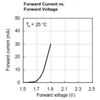
Step 3: Determine the Forward Voltage
For our example using the Kingbright WP7113SRD/E red LED: from the Forward Current vs. Forward Voltage chart, at 20mA the forward voltage is approximately 1.85V. Use the table from Section 3 as a starting point for other colors, or measure directly with a multimeter in diode mode.
Step 4: Calculate the CLR
The CLR is calculated using Ohm’s Law, accounting for the voltage drop across the LED (Equation 7.1):

In our example, we get a CLR resistance of (9 – 1.85) / 0.020A = 7.15V / 0.020A = 357.5 Ω.
The nearest standard E24 resistor value above 357.5Ω is 390Ω. Using 390Ω slightly reduces the forward current, keeping the LED within a safe and bright operating range.
⚠️Note: 390Ω at 9V produces a very bright indicator. Most modern high-efficiency LEDs are uncomfortably bright at 20mA. A starting value of 1kΩ – 2.2kΩ is more practical for typical pedal use.
You can also use the Stompbox Electronics online CLR resistance calculator to calculate the CLR value automatically.
CLR Quick Reference Table at 9V Supply
The table below provides pre-calculated CLR values for the most common LED colors at three brightness levels, assuming a 9V supply. Values are rounded to the nearest standard E24 resistor resistor. Use these as starting points – your specific LED’s Vf may differ slightly from the typical values used here.
| LED Color | Dim (5mA) | Medium (10mA) | Bright (20mA) |
|---|---|---|---|
| Red (Vf ≈ 1.8V) | 1.5kΩ | 750Ω | 360Ω |
| Orange (Vf ≈ 2V) | 1.3kΩ | 680Ω | 360Ω |
| Yellow (Vf ≈ 2.2V) | 1.3kΩ | 680Ω | 330Ω |
| Green (Vf ≈ 3.5V) | 1.1kΩ | 560Ω | 270Ω |
| Blue (Vf ≈ 3.6V) | 1.1kΩ | 560Ω | 270Ω |
| White (Vf ≈ 3.3V) | 1.1kΩ | 560Ω | 270Ω |
Brightness tip: Increase the CLR value to dim the LED; decrease it to brighten. The practical sweet spot for most indicator LEDs at 9V is between 1kΩ and 2.2kΩ.
Troubleshooting: Common LED Indicator Problems
The indicator LED circuit is simple enough that problems almost always come down to one of four causes.
| Symptom | Likely Cause & Fix |
|---|---|
| LED does not light up | Check polarity first: flip the LED. Then verify CLR is installed and there is continuity from supply through the LED path to ground. Check switch wiring in 3PDT builds. |
| LED is too bright / harsh | Increase the CLR value. At 9V, most modern LEDs are comfortable at 1kΩ – 2.2kΩ. Start at 2.2kΩ. |
| LED is too dim | Decrease the CLR value, or recalculate using the correct Vf for your LED color. Blue and white LEDs have higher Vf (≈3.3–3.6V) and will be noticeably dimmer if a CLR was calculated for a red or orange LED. |
| LED flickers when engaging footswitch | Usually a grounding issue in the 3PDT wiring. Check that the LED ground path through the switch is solid, that the footswitch lugs are correctly wired, and whether there is continuity between the switch lugs. |
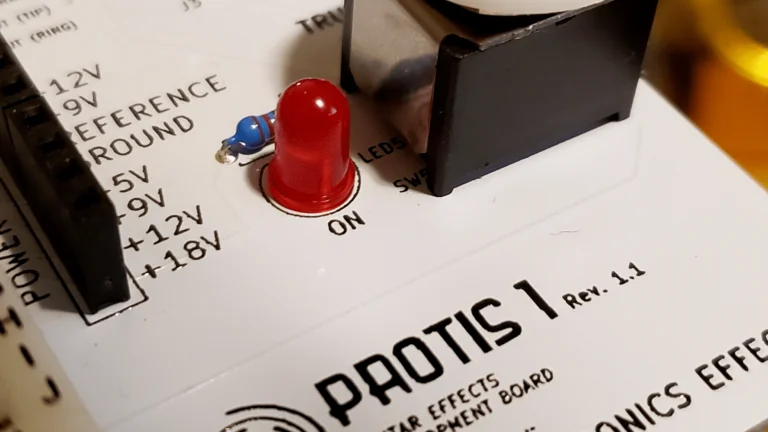
Wiring the LED into the Pedal
On its own, the LED circuit simply indicates that power is present. Some vintage designs use it that way – the big-box EHX Deluxe Memory Man’s indicator LED is always on when the pedal is powered. In most modern builds, you want the LED to indicate bypass state (on when engages, off when bypassed).
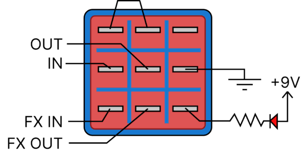
The standard approach is to use the third pole of a 3PDT footswitch to control the LED’s ground connection. When the switch is in the engaged position, the third pole completes the ground path and the LED lights. When bypassed, it breaks the ground path and the LED goes dark. This is the same 3PDT switch covered in Circuit 1: The Bypass.
⚠️Important: Never connect an LED directly across a power supply without a CLR. Doing so will burn out the LED almost immediately.
Indicator LED Circuit Parts List
Use the following components to experiment with the LED indicator circuits on a breadboard or the PROTIS 1 development board.
| Parts | Qty |
|---|---|
| Red LED, 5mm diffused | 1 |
| Yellow LED, 5mm diffused | 1 |
| Green LED, 5mm diffused | 1 |
| Orange LED, 5mm diffused | 1 |
| Blue LEDs, 5mm diffused | 1 |
| Bicolor LED, 2-lead red/green, 5mm | 1 |
| 390Ω Resistor | 1 |
| 1kΩ Ohm Resistor | 2 |
| 2.2kΩ Ohm Resistor | 1 |
| 4.7kΩ Ohm Resistor | 1 |
References
[1] Circuit 1 of 48: The Bypass – 3PDT footswitch wiring that controls the LED indicator
[2] Circuit 4 of 48: Diode Protection – Diode fundamentals including forward voltage, anode, and cathode
[3] Stompbox Electronics CLR Calculator – Calculate the CLR value for any LED and supply voltage combination.
[4] Series/Parallel Resistance Calculator – Combine standard resistors to achieve non-standard CLR values.
[5] Kingbright WP7113SRD/E Datasheet – Datasheet for the red LED used in the worked examples in this article
Guitar Effects Design in 48 Circuits or Less
This post is part of the 48 Circuits or Less series by Stompbox Electronics. Each installment covers one fundamental pedal circuit building block – concept, demonstration, and supplemental resources.
View more articles in this series here.
Meet the Author:

Hi, I’m Dominic. By day, I’m an engineer. By night, I repair and modify guitar effects! Since 2017, I’ve been independently modifying and repairing guitar effects and audio equipment under Mimmotronics Effects in Western New York. After coming out with a series of guitar effects development boards, I decided the next step is to support that community through content on what I’ve learned through the years. Writing about electronics gives me great joy, particularly because I love seeing what others do with the knowledge they gain about guitar effects and audio circuits. Feel free to reach out using the contact form!
The Tools I Use
As a member of Amazon Associates, Stompbox Electronics earns and is supported by qualifying purchases.


