

BOSS effects are a staple of the industry, but sometimes it can be difficult to see the indicator LEDs. In this article we go over a couple ways you can increase the brightness of the LED in your BOSS effects pedal. Both involve simple modifications, so get your soldering iron ready!

As a member of the Reverb Partner Program, eBay Partner Network, and as an Amazon Associate, StompboxElectronics earns from, and is supported by, qualifying purchases.
Disclaimer: Stompbox Electronics and/or the author of this article is/are not responsible for any mishaps that occur as a result of applying this content.
What Type of LEDs are Used in BOSS Pedals?
Before going into the ways we can up the brightness, it helps to know what we’re working with.
BOSS compact pedals most commonly use 3mm Red LEDs for their indicator lights. Usually, the LED part number for a particular BOSS pedal can be found in the corresponding service manual (if you can find it).
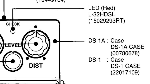
For example, the BOSS DS-1 service manual calls out an L-32HDSL on the first page.
Even though it seems like every BOSS pedal has the same 3mm red LED, the actual part number changes a bit between models. Here’s a short list of LED part numbers for different BOSS pedals, according to their service manuals:
| BOSS Pedal | LED Part Number | Forward Current (Typ.) | Forward Voltage (Typ.) |
|---|---|---|---|
| BOSS DS-1 | Kingbright L-32HDSL | 25mA | 2.5V |
| BOSS SD-1 / BOSS HM-2 / BOSS OC-2 | Sanyo SLP-135B | 25mA | 1.9V |
| BOSS DD-3 / BOSS TR-2 / BOSS RV-3 | Panasonic LN-28RP | 15mA | 2.2V |
Method #1: Choose a Replacement LED for Your BOSS Pedal
The first method we can consider is replacing the LED altogether.
1. Choosing a Replacement
First, you’ll have to choose a replacement LED. You can compare LEDs using a property called luminous intensity.
Luminous Intensity (mcd)
Luminous intensity is exactly what it sounds like: the intensity of brightness. It’s given in units of millicandelas (mcd) and can be found in the datasheet of the LED. The higher the mcd value, the more intense the light. Here are the mcd values for the LEDs we mentioned earlier:
| LED Part Number | Luminous Intensity (mcd) |
|---|---|
| L-32HDSL | 1.4 mcd (min=0.8, max=2.0) |
| SLP-135B | 1.2 mcd |
| LN-28RP | 0.8 mcd |
You can find 3mm LEDs and sort by mcd and lens type using filters from popular electronics distribution sites. Some examples that come to mind are Mouser, DigiKey, and Newark.
2. New LED Installation
Now that you have a replacement LED you can start to install it. The process is pretty straightforward, just follow the steps below.
Getting to the LED
First, unscrew the 4 screws holding in the backplate of the pedal and remove the plastic insulator to reveal the circuit board. Carefully move the main board out of the way in order to access the LED board.
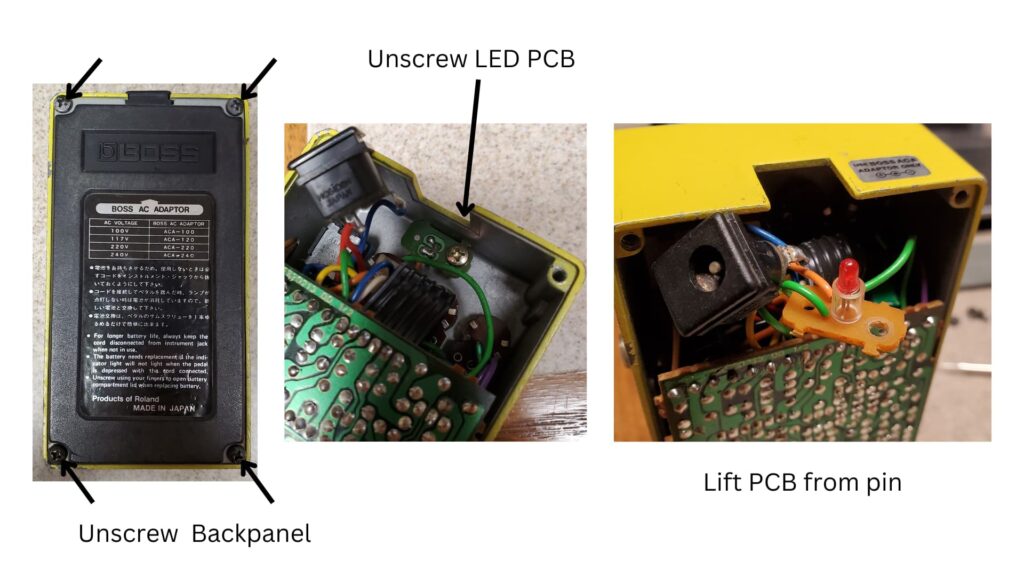
Removing the Old LED
Next up, you’ll need to remove the LED. This part seems straightforward, simply desolder the LED and you’re all set. Not so fast! There is a right way to do this.
First off, I would recommend using a soldering iron with temperature setpoint capability. I personally use the Weller WE1010EDU, but other models have their fans as well (the Hakko FX888D comes to mind). If you’d like a dedicated tool for this, the Hakko FR301 Desoldering Gun is a great option. All are usually available on Amazon at the links provided.
Now, preheat your soldering iron to between 370°C (700°F) and 400°C (750°F). Apply heat to each of the pads and gently remove the LED.
Note that it’s always possible that the traces on the LED board could lift up and become disconnected, ruining the board. To avoid this, apply heat to the pad until you are confident you can pull the LED through the via.
Cleaning Out the Solder Holes
Now that the LED is out, there may be leftover solder in the vias. We’ll need those vias to install the new LED, so we need to make sure that solder is cleared out. There are a couple ways you can do this.
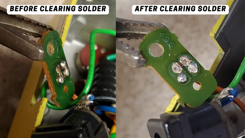
You’ll want to use a combination of your soldering iron and a desoldering pump. The idea is to heat the pad up for about 3-10 seconds, then quickly move the desoldering pump over the via to suck out the solder. Alternatively, the Hakko FR301 is great for this step as well.
Installing the New LED
The old LED has been removed and now it’s time to solder in the new one! Remember, LEDs have polarity. Mind the marking on the LED board. If there is no marking, you can look up the schematic of your BOSS pedal and check to see where each of the wires land on the main board. That should give you an idea of the polarity of the LED.
Method #2: Change the Current Limiting Resistor
Another way to increase the LED brightness on your BOSS pedal is to lower the value of the current limiting resistor, or CLR.
The CLR’s job is to limit the current flowing through the LED so it doesn’t burn out due to over-current. All we need to do is make sure the resistance is high enough so the LED doesn’t draw excessive current, and low enough to satisfy our needs for a brighter LED.
Read more about the CLR circuit here
In order to replace the current limiting resistor we will need to know two things:
- Where the CLR is located, and
- What value resistance is it?
Once we know those two things we’ll be able to use this Indicator LED Current Limiting Resistor Calculator to figure out a new value for the CLR.
1. Finding Your BOSS Pedal’s CLR
The first step is finding the resistor. This information is usually shown in the BOSS pedal’s service manual. I’ve done the work for a handful of BOSS pedals below and listed out the component designations and resistance values.
List of BOSS Pedal Current Limiting Resistors
| BOSS Pedal | Resistor Designation | Resistance Value |
|---|---|---|
| BOSS AC-2 | R6 | 1.8kΩ |
| BOSS AC-3 | R73 | 1kΩ |
| BOSS AW-2 | R67 | 1.2kΩ |
| BOSS BF-2 | R63 | 3.9kΩ |
| BOSS CE-2 | R51 | 3.9kΩ |
| BOSS CE-2B | R51 | 3.9kΩ |
| BOSS CE-3 | R13 | 3.9kΩ |
| BOSS CS-1 | (not marked) | 1kΩ |
| BOSS CS-3 | R35 | 3.3kΩ |
| BOSS DF-2 | R25 | 2.2kΩ |
| BOSS DM-2 | R40 | 3.9kΩ |
| BOSS DM-3 | R43 | 2.2kΩ |
| BOSS DS-1 | R35 | 3.9kΩ |
| BOSS GE-7/GE-7B | R10 | 3.9kΩ |
| BOSS HF-2 | R63 | 3.9kΩ |
| BOSS HM-2 | R46 | 2.2kΩ |
| BOSS OC-2 | R25 | 3.9kΩ |
| BOSS OD-1 | (not marked) | 1kΩ |
| BOSS OD-2 | R53 | 1.2kΩ |
| BOSS PH-1r | R48 | 3.9kΩ |
| BOSS PH-2 | R82 | 2.2kΩ |
| BOSS SD-1 | R30 | 3.9kΩ |
| BOSS SG-1 | R37 | 3.9kΩ |
| BOSS SP-1 | R27 | 3.9kΩ |
| BOSS TW-1 | R45 | 3.9kΩ |
| BOSS VB-2 | R51 | 3.9kΩ |
2. Determining the LED Forward Voltage
The goal is to use the online CLR calculator to figure out the replacement resistor value. There is a field for “Forward Voltage” which we will need to determine. I went through each service manual in the table above and listed the LED part number that each one uses below, along with the forward voltage value.
| BOSS Pedal | LED Part Number | Forward Voltage (V) |
|---|---|---|
| BOSS AC-2 | L-34HDSL | 2.5V |
| BOSS AC-3 | L-34HDSL | 2.5V |
| BOSS AW-2 | LN-28RP | 2.2V |
| BOSS BF-2 | SLP-135B | 1.9V |
| BOSS CE-2 | SLP-135B | 1.9V |
| BOSS CE-2B | SLP-135B | 1.9V |
| BOSS CE-3 | SLP-135B | 1.9V |
| BOSS CS-1 | GL-32AR* | 1.7V |
| BOSS CS-3 | LN-28RP | 2.2V |
| BOSS DF-2 | SLP-135B | 1.9V |
| BOSS DM-2 | SLP-135B | 1.9V |
| BOSS DM-3 | SLP-135B | 1.9V |
| BOSS DS-1 | L-34HDSL | 2.5V |
| BOSS GE-7/GE-7B | GL-3PR2** | datasheet not found |
| BOSS HF-2 | LN-28RP | 2.2V |
| BOSS HM-2 | SLP-135B | 1.9V |
| BOSS OC-2 | SLP-135B | 1.9V |
| BOSS OD-1 | GL-32AR* | 1.7V |
| BOSS OD-2 | not known, probably GL-32AR* | 1.7V |
| BOSS PH-1r | SLP-135B | 1.9V |
| BOSS PH-2 | SLP-135B | 1.9V |
| BOSS SD-1 | SLP-135B | 1.9V |
| BOSS SG-1 | GL-32AR | 1.7V |
| BOSS SP-1 | SLP-135B | 1.9V |
| BOSS TW-1 | SLP-135B | 1.9V |
| BOSS VB-2 | SLP-135B | 1.9V |
**GL-3PR2: Datasheet not found, direct replacement not found.
3. Calculating the Stock Forward Current
Now that you have the forward voltage value and the CLR value currently being used, use the calculator to calculate the forward current. Enter 9 in the Voltage Supply field, along with the Forward Voltage and the CLR value that you obtained earlier. Then, click the Value to Calculate dropdown and choose Forward Current.
For example, here is what my calculator looks like for a BOSS DS-1 after hitting calculate.
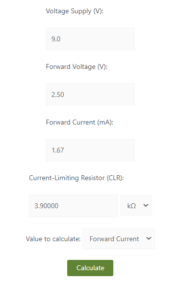
The calculated forward current is about 1.67mA for the BOSS DS-1 circuit.
4. Determine the Replacement CLR
Now that we have an idea of what the stock pedal is doing, we can start figuring out a new CLR value to use. To do that, keep all values the same on the calculator, but change the Value to Calculate dropdown to “CLR”.
Typically, the higher the forward current, the more intensity is produced by the LED. The maximum value you can go depends on the pedal and LED specifications (given in the table above). It is highly advised that you do not try to run the LED at the maximum current. Instead, start by increasing the Forward Current field by 1 or 1.5mA and see what CLR value that produces. Then, install the resistor and see if it works for you.
In the BOSS DS-1 example above, I changed the Forward Current value of 1.67mA to 3mA. That yielded a CLR value of 2.167kΩ, and the closest resistor I have to that is 2.2kΩ.
5. Replacing the Resistor
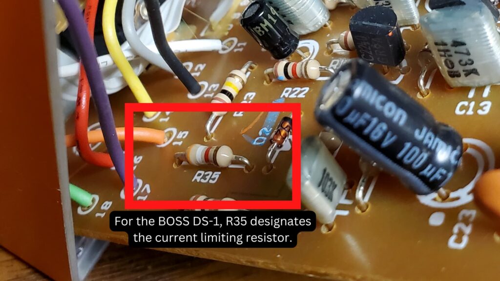
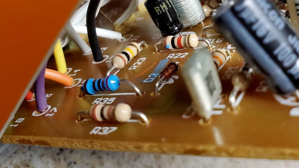
First, locate the current limiting resistor using the designation in the table above. For the BOSS DS-1 the designation is R35.
Once you’ve found it, you’ll want to heat up your soldering iron. A good temperature should be between 700-750 degrees Fahrenheit. I usually keep mine at 715 degrees and adjust as needed.
One step I like to do before removing a component is to reflow the solder on both resistor pads. This introduces flux to the solder connections and helps with thermal dissipation when removing the solder in a later step.
After reflowing the solder, the next step is to remove the resistor. I usually approach this like I put on my pants: one leg at a time. Using a pair of insulated tweezers, I gently (very gently!) lift one side of the resistor while heating the pad with the iron. Be very careful not to rip off the copper pad or trace, which can happen if you lift the component before the solder has a chance to fully melt.
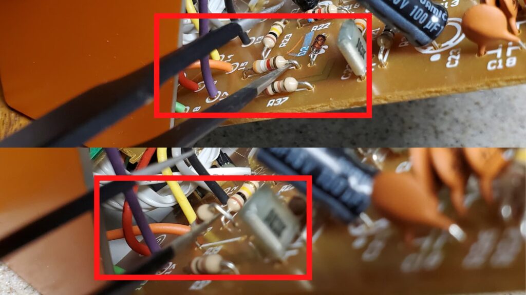
When one end of the resistor is lifted you can simply heat up the other lead and gently remove the whole resistor with the pair of tweezers.

Next, there will probably be solder left over in the holes that the resistor once occupied, so do your best to clean that out. There are a few tools you can use for this, the most common being desoldering braid or desoldering pumps. Use whichever is more comfortable for you.
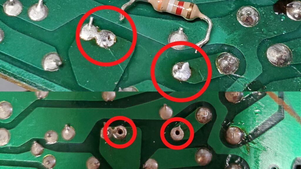
After cleaning out the remaining solder, the last step is to install the new resistor. There’s no polarity here, so you don’t need to worry about which leg goes in which hole. Just slide it in, solder it up and test it out.
If it’s too bright, then go with a higher value!
Meet the Author:

Hi, I’m Dominic. By day, I’m an engineer. By night, I repair and modify guitar effects! Since 2017, I’ve been independently modifying and repairing guitar effects and audio equipment under Mimmotronics Effects in Western New York. After coming out with a series of guitar effects development boards, I decided the next step is to support that community through content on what I’ve learned through the years. Writing about electronics gives me great joy, particularly because I love seeing what others do with the knowledge they gain about guitar effects and audio circuits. Feel free to reach out using the contact form!
The Tools I Use
As a member of Amazon Associates, Stompbox Electronics earns and is supported by qualifying purchases.


