
The Behringer UV300 Rate Mod
If you landed here, you’re probably looking for instructions on how to modify your Behringer UV300 with the popular Rate Mod. It’s often expressed that the minimum Rate setting is too fast for many applications. This mod reduces the range of the Rate control so you can access slower vibrato settings.

As a member of the Reverb Partner Program, eBay Partner Network, and as an Amazon Associate, StompboxElectronics earns from, and is supported by, qualifying purchases.
Disclaimer: Stompbox Electronics and/or the author of this article is/are not responsible for any mishaps that occur as a result of applying this content.
Note: Credit goes where credit is due. It has come to my attention that Paul from “Paul in the Lab” is the brain behind this modification.
Understanding the LFO Circuit
It’s commonly known that the UV300 is a clone of the BOSS VB-2. While part designations for both pedals don’t exactly match, we can get a good idea of which components to modify from the VB-2. In this article we’ll only dive into what we need for the mod. You can always read more about the circuit here.
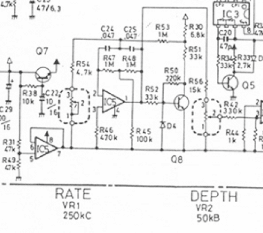
Here’s the VB-2 schematic for reference.
Modeling the LFO
The VB-2 LFO circuit matches the one used in the Behringer UV300. In this post, I want to give special attention to the components responsible for Rate adjustment, particularly capacitors C24 and C25 (near the top).
The LFO is made up of two main circuit blocks: an Op Amp Filter and a Transistor Clipper. Our attention is focused on the Op Amp Filter, which is modeled below. A voltage source V5 produces a square wave at 2Hz for simulation purposes.
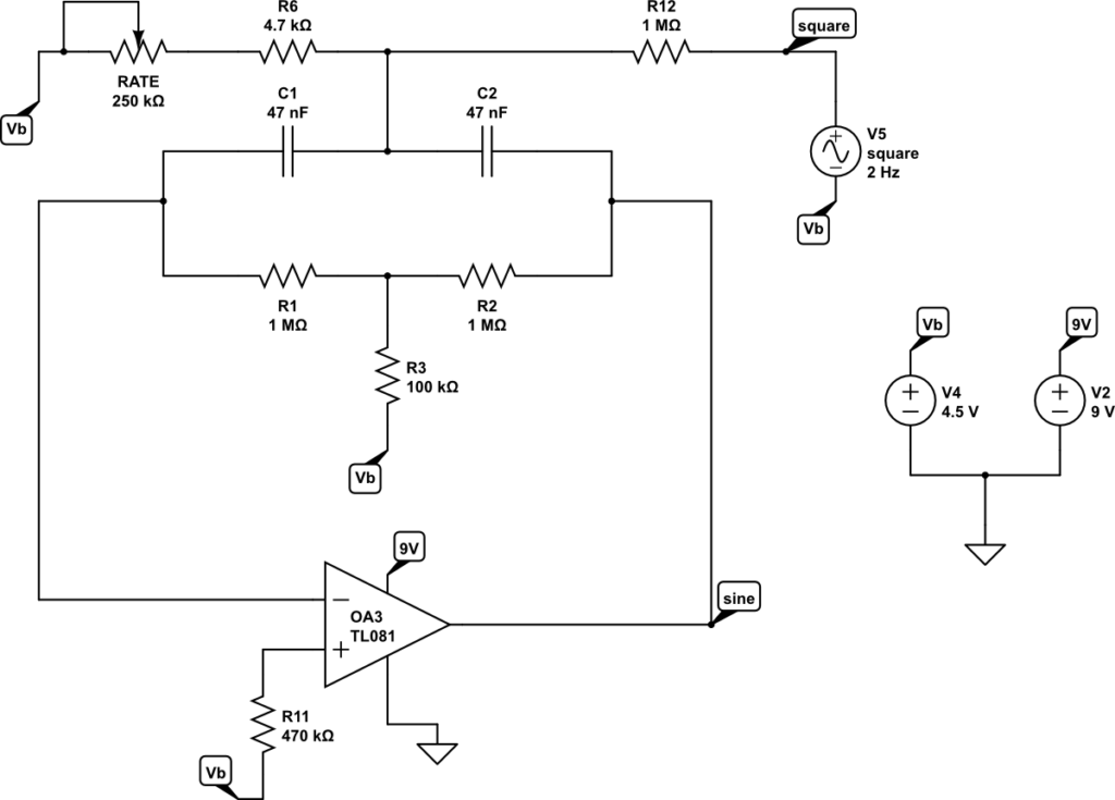
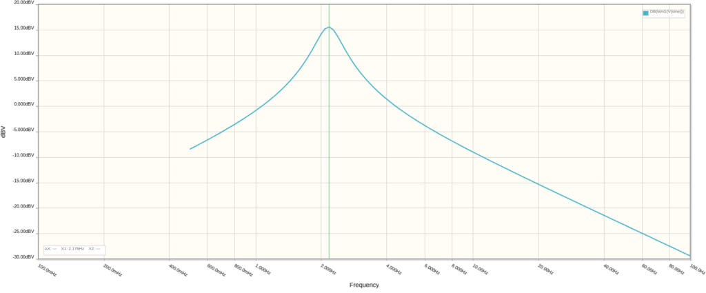
We can find the oscillation frequency for particular component values by running a frequency sweep on V5 and observing where the peak is on the frequency plot. In this case, when the Rate knob is all the way down, the oscillation frequency is about 2.2Hz.
Modeling Adjustments in C24 and C25
Usually, to simplify the type of filter network used in the Op Amp Filter, capacitors C24 and C25 are set equal to eachother. Fortunately, this simplification was followed in both the VB-2 and the UV300 circuits. For this mod we’ll do the same for each capacitor value. So, capacitance C = C24 = C25.
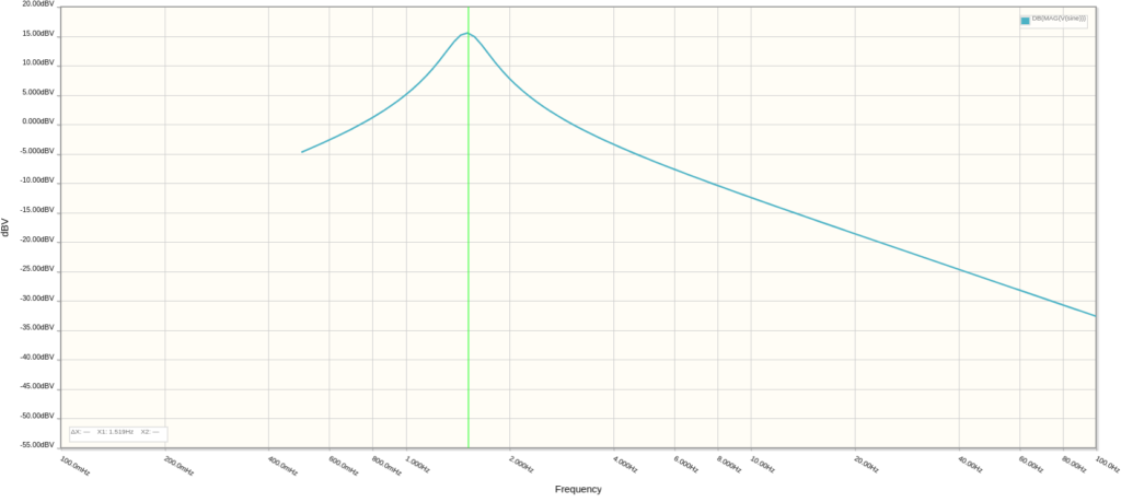
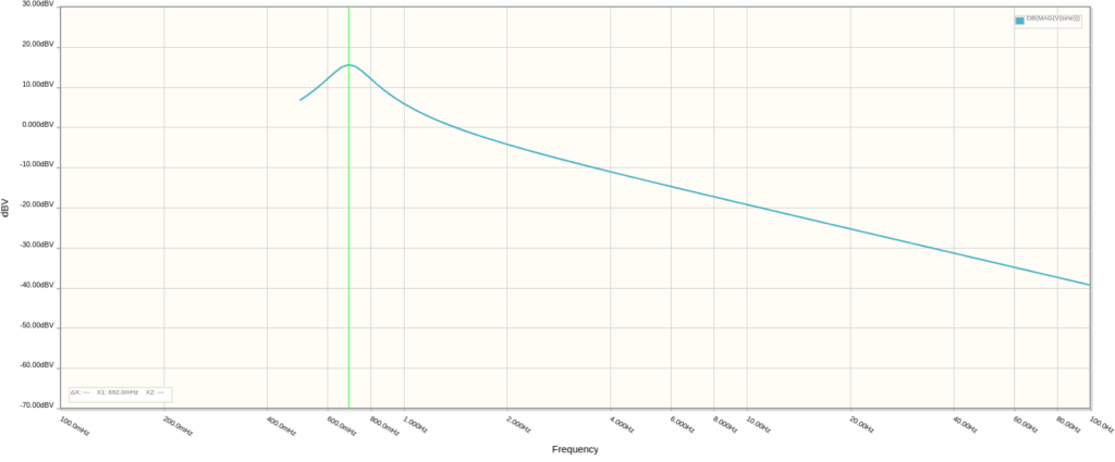
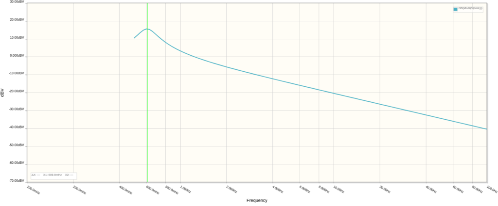
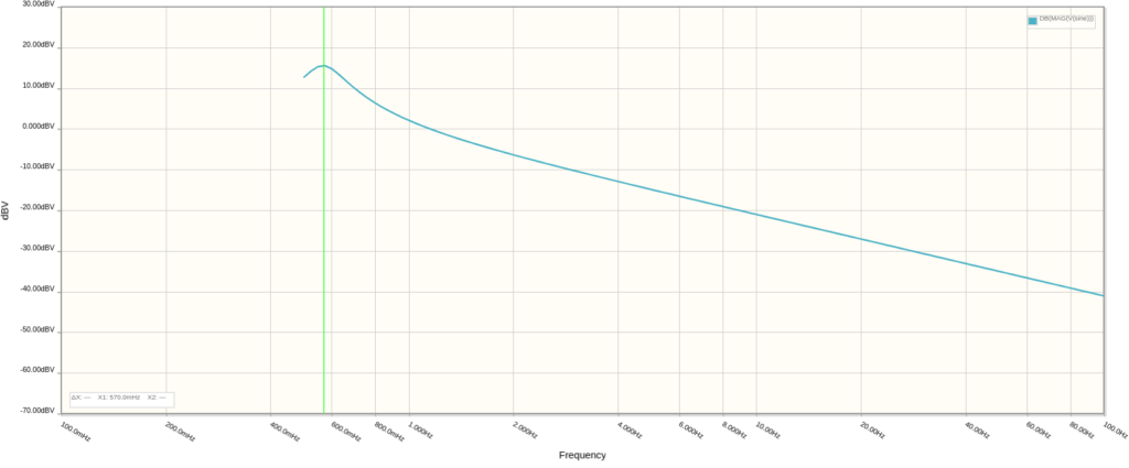
The following plots were made with C = 68nF, 100nF, 147nF, 168nF, and 180nF.
Frequency Response with C = 68nF
Frequency Response with C = 100nF
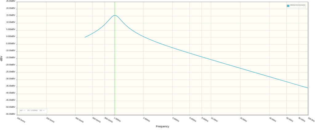
Frequency Response with C = 147nF
Frequency Response with C = 168nF
Frequency Response with C = 180nF
How to Open the Behringer UV300
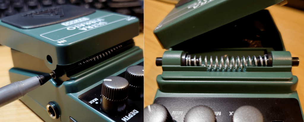
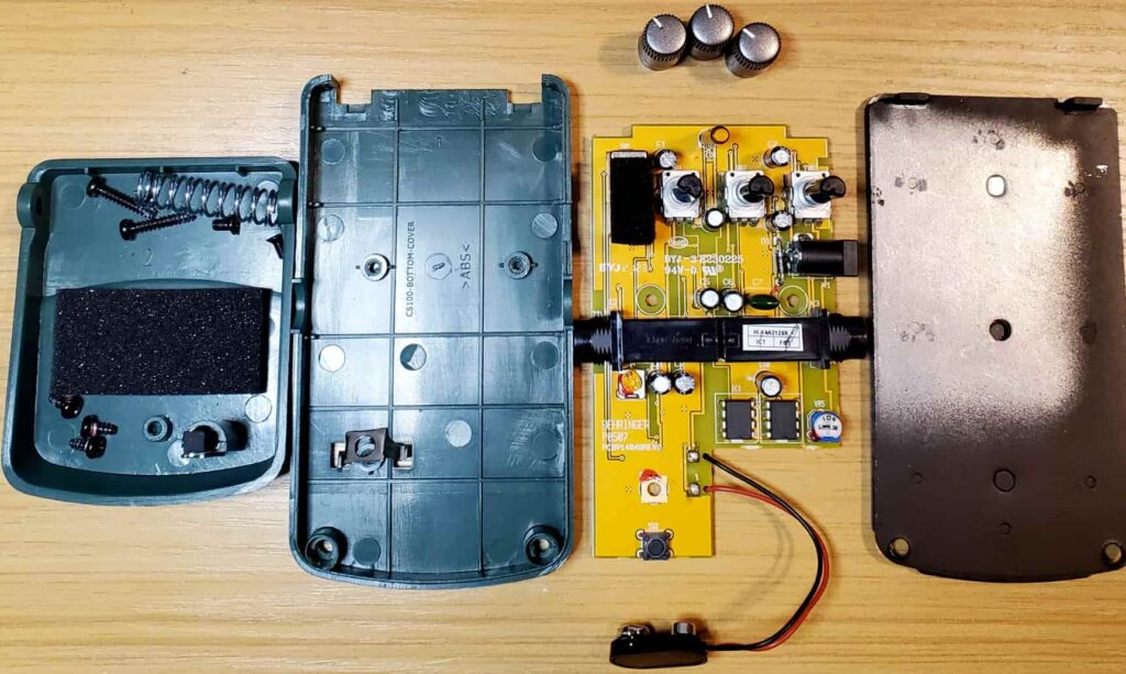
First, you need to open up the Behringer pedal. Take off the top plastic cover by pushing a pen tip into either side of the black spring plunger. Use the photo below as a reference.

Then, there are four screws you will need to remove: two on the bottom of the enclosure and two on the top.After removing those, you should end up with the following:
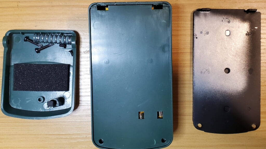
To remove the plastic cover, you will need to slide off the knobs. Once you take off all three mods, open the case and push the battery clip through the hole.
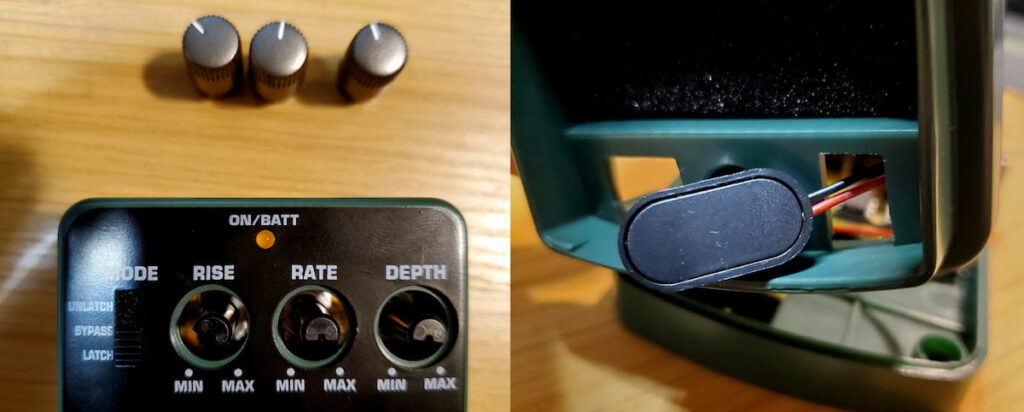
On the circuit board there are three black screws to remove. Unscrew all three.
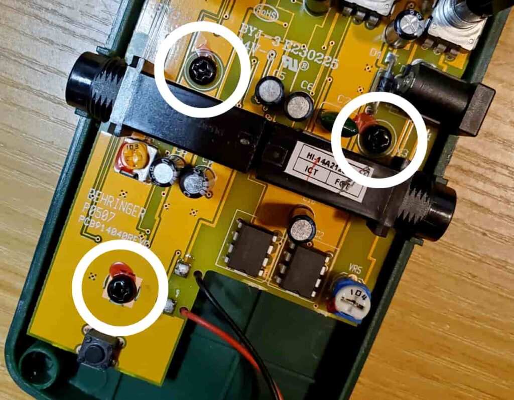
You have successfully removed the circuit board from the UV300.
Performing the UV300 Rate Mod
With the plots a few sections ago we now know that, if you adjust the capacitors in the op amp filter network, you can reduce the minimum Rate setting from 2 Hz all the way down to around 0.6Hz. That’s a big achievement! Note that for capacitance values above 180nF the plots showed no peak, so it’s safe to assume that 0.5Hz may be the lower limit here.
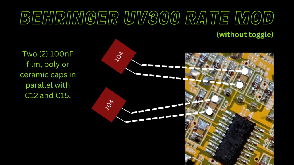
For me, 147nF was enough. Since the capacitors used in the stock circuit are both 47nF, all you need to do is solder a 100nF capacitor in parallel with each of them.
Locating the Capacitors
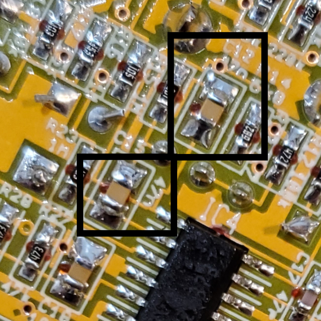
Luckily, Behringer silk-screened the capacitor values onto the circuit board itself, so it’s a little easier to find them. Look for the two caps connected together with values of 47nF.
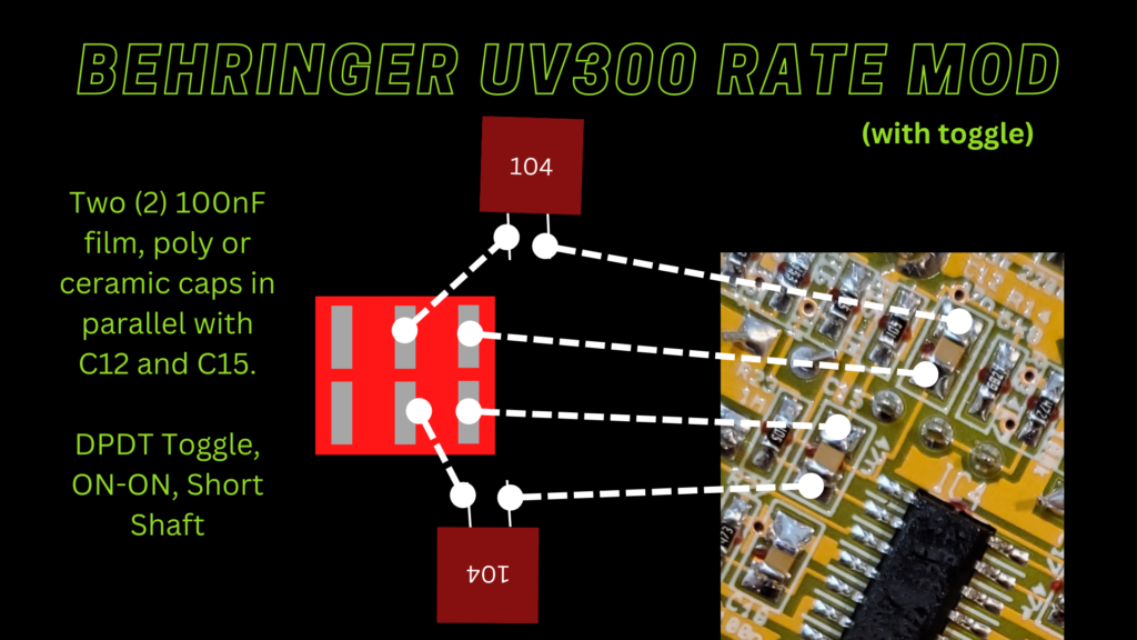
You can also go by the component designations. For the UV300, the designations are C12 and C15, and you can find them near the op amp chip IC4. To be precise, C12 is the capacitor connected to the output of the op amp. C15 is the capacitor connected to the inverting input.

Choosing Your Capacitor Value
For this mod, we’re going to put two (2) 100nF capacitors in parallel with each of the existing 47nF caps. When you place capacitors in parallel, the capacitance values add up. So, 47nF + 100nF = 147nF. See this calculator to play around with difference capacitance values.
The type of capacitor is important. Don’t use electrolytics! They simply won’t work for this application. Use a poly-type or ceramic. The short code for 100nF is 104, so the new caps should have that printed on their body. It’s always helpful to have an assortment of capacitors available to you when performing modifications. You can find assorted capacitor kits on Amazon.
Keeping the Stock Option
If you want to be able to keep the stock range in tact, but still want the lower range from the mod, then you can install a toggle switch to choose one or the other. The type of switch you’ll need here is an ON-ON DPDT toggle, short shaft (available at LoveMySwitches or possibly Tayda).
Wire Up the Mod
Now that you have the parts and an idea of the range you’re going for, we can start wiring everything up. If you don’t care to have the toggle switch, then it’s as simple as wiring the two capacitors in parallel (schematic #1).
If you would rather have the choice that the toggle switch gives you, you can use the second schematic below.
Tip on Soldering the Wires
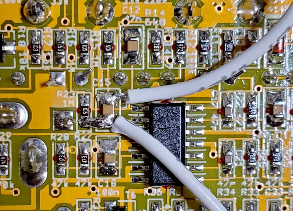
Soldering the wires to the circuit board can be tricky, especially on a PCB with surface-mount components. Make sure you strip the wire so the exposed wire is as short as possible. Tin the wire and the solder pad before soldering the actual connection.
Here’s an example of the C15 cap soldered and ready to go. Note that the lower wire extends over to one of R23’s solder pads. That’s only because there is already a trace underneath that connected the two pads, so the overlap wasn’t a big deal. Be attentive otherwise.
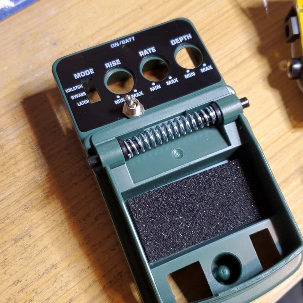
Installing the Toggle Switch
The best place for the toggle switch is just below the Rise knob. Punch a small dent into the plastic, making sure the body of the toggle switch will fit the internal space. Then, drill a 1/4″ hole for the toggle switch.

Reassemble and Enjoy
The last step is to simply reassemble the pedal. Start by screwing the PCB back into the plastic case with the three black screws. Then, fit the enclosure back on top and put the knobs back on. Screw in the metal back plate, then snap in the plastic battery cover.
Meet the Author:

Hi, I’m Dominic. By day, I’m an engineer. By night, I repair and modify guitar effects! Since 2017, I’ve been independently modifying and repairing guitar effects and audio equipment under Mimmotronics Effects in Western New York. After coming out with a series of guitar effects development boards, I decided the next step is to support that community through content on what I’ve learned through the years. Writing about electronics gives me great joy, particularly because I love seeing what others do with the knowledge they gain about guitar effects and audio circuits. Feel free to reach out using the contact form!
The Tools I Use
As a member of Amazon Associates, Stompbox Electronics earns and is supported by qualifying purchases.


