
By: Dominic Sciarrino | Stompbox Electronics | Last Published: February 27th, 2026
As a member of the Reverb Partner Program, eBay Partner Network, and as an Amazon Associate, StompboxElectronics earns from, and is supported by, qualifying purchases.
Disclaimer: Stompbox Electronics and/or the author of this article is/are not responsible for any mishaps that occur as a result of applying this content.
Introduction
Plug in the wrong polarity power supply – even briefly – and the results can be immediate and expensive. Electrolytic capacitors fail catastrophically. ICs and transistors conduct in the wrong direction. Reverse voltage can destroy a circuit in seconds.
The fix can be as simple as adding a single component: the diode. One component, placed correctly, can completely block a reversed polarity supply from ever reaching your circuit. There are two ways to place it – series and parallel – and each approach has real tradeoffs worth understanding before you commit to an approach.
This post introduces the diode as a component, explains how forward voltage drop affects your design decisions, and covers both protection topologies in detail – including the failure modes that other sources may not discuss.
Part 1: The Diode
Component Overview
A diode is a two-terminal semiconductor component. The two terminals are the anode and the cathode. Current can flow through a diode in one direction only: from anode to cathode. Attempt to push current the other way (from cathode to anode) and the diode blocks it.
On the schematic symbol, the anode is on the flat side of the triangle (the arrowhead points toward the cathode). On a physical diode, the cathode is marked with a painted stripe around the body.
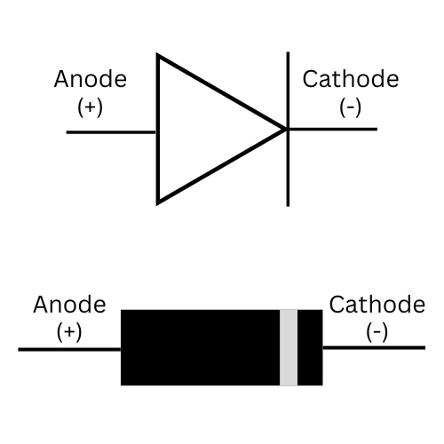
Two memory aids for keeping the terminals straight:
- Anode: the word starts with A, and the schematic symbol has a triangle – the pointy top of an A. The triangle side is the anode.
- Cathode: marked with a stripe. A stripe is a line. A minus sign is a line. The cathode is the negative terminal.
Forward Voltage Drop
When a diode conducts (i.e. when current flows from anode to cathode) it doesn’t pass voltage through transparently. It drops a small, roughly fixed voltage across itself. This is the forward voltage drop.
For a standard silicon rectifier diode (such as the 1N4001), the forward voltage drop is approximately 0.6 to 0.7 volts under typical current conditions. For a Schottky diode (such as the 1N5817), the drop is lower – approximately 0.2 to 0.35 volts at low-to-moderate current levels.
Forward voltage drop is not a fixed value – it increases with current. The 0.65V figure for silicon and 0.2-0.35V for Schottky are representative at the low current draws typical of guitar pedals (under 50mA). At higher currents, both values rise. Always check the datasheet for your specific diode and expected current.
Part 2: Guitar Pedal Power Supply Polarity
The industry standard for guitar pedal power supplies is center negative: the inner pin of the barrel connector connects to ground, and the outer barrel connects to the positive supply rail (see Figure 4.3). BOSS established this standard and virtually every modern pedal manufacturer adopted it.
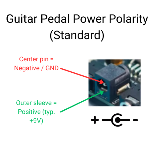
Center negative is the opposite of most consumer electronics, which use center positive connectors. Generic wall-adapters, laptop chargers, and unregulated AC adapters all operate differently from guitar-pedal-specific supplies. Using the wrong one, even at the correct voltage, can result in reverse polarity at the pedal’s power jack.
This is why purpose-built pedalboard power supplies (like Voodoo Lab, Strymon Zuma, or similar) exist. They guarantee correct polarity and regulated voltage on every output. If you are powering pedals with generic wall adapters, reverse polarity protection is not optional – it is essential.
Part 3: Series Diode Protection
The series diode is placed in-line between the power supply input and the circuit. The anode faces the power supply; the cathode faces the circuit.
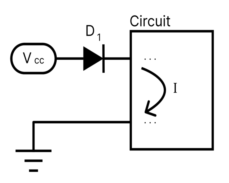
In normal operation with correct polarity, the diode is forward biased. Current flows from anode to cathode and through the circuit. The pedal operates normally, with the forward voltage drop as the only cost.
If the supply is reversed, the cathode is now at higher potential than the anode. The diode is reverse biased, therefore no current flows. The circuit is completely isolated from the reversed supply voltage.
The Voltage Drop Tradeoff: Silicon vs. Schottky
Series diode protection has one primary cost: the forward voltage drop. For a 9V supply with a silicon diode, approximately 8.35V reaches the circuit. For most pedal designs this is acceptable – bias voltages derived from the supply shift proportionally, and the circuit still functions correctly. But it is a real reduction, and for circuits designed specifically to operate at exactly 9V, it is worth addressing.
The practical solution is to use a Schottky diode instead of a silicon rectifier. The 1N5817 is the most commonly used Schottky in DIY guitar pedal designs. At typical pedal current draws, its forward drop is in the 0.2 to 0.35 volt range – recovering significant headroom compared to silicon.
| Silicon Rectifier (1N4001) | Schottky (1N5817) | |
|---|---|---|
| Forward Voltage Drop | ~0.65V | ~0.2-0.35V * |
| Supply Voltage at 9V in | ~8.35V | ~8.65 – 8.8V |
| Reverse Blocking Voltage | 50V | 20V |
| Reverse Leakage Current | Very low | Slightly higher |
| Cost (approx. retail) | <$0.10 each (as of 2026) | ~$0.20-0.40 each (as of 2026) |
| Common pedal part | 1N4001 | 1N5817 |
The 1N5817 has a lower reverse blocking voltage (20V vs. 50V for the 1N4001), but for standard 9V to 18V pedal power supplies this is adequate. Its reverse leakage current is also slightly higher, which is relevant in precision analog circuits, but inconsequential in most pedal power applications.
For most DIY guitar pedal builds, the 1N5817 Schottky is a strong default choice for series protection. The lower voltage drop is a genuine improvement over the 1N4001, the cost difference is almost negligible, and the part is widely available. Keep both in your component stock.
Where Series Protection Appears in Commercial Designs
BOSS compact series pedals used series diode protection throughout their ACA-power era. The diode was placed in series with the supply rail on the main PCB, and its forward voltage drop was actually accounted for in ACA supply specifications – which is why ACA pedals behave differently with standard PSA supplies. (See the ACA-to-PSA conversation article for more on this.)
Series protection also appears in numerous boutique and DIY designs where a small voltage reduction is acceptable and the simplicity of a single in-line component is preferred.
Part 4: Parallel (Shunt) Diode Protection
The parallel diode – sometimes called a shunt diode or crowbar diode – is placed across the power rails rather than in series with them. The anode connects to the negative supply rail (ground), and the cathode connects to the positive supply rail. This is the reverse of how a diode normally conducts.
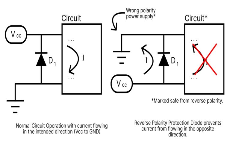
In normal operation with correct polarity, the diode is reverse biased. It does nothing. The full supply voltage reaches the circuit – no forward voltage drop, no voltage reduction.
When a reversed polarity supply is connected (as shown in Figure 4.5 on the right), the polarity across the diode flips. The diode is now forward biased and conducts heavily, creating a near-short across the supply rails. The voltage across the circuit is clamped to approximately one diode drop – not enough to damage anything. The circuit is protected.
The Parallel Diode Failure Modes
The parallel arrangement has a vulnerability that matters in practice: when the diode conducts under reversed polarity, it is absorbing all the energy the power supply can deliver. The supply is pushing current; the diode is dissipating it as heat. How long the diode survives this depends on its power rating, the supply’s current capacity, and how quickly someone notices and unplugs.
If the reverse polarity event is brief, the diode will likely survive and the circuit will be unharmed. If sustained, the diode overheats and fails. How it fails determines what happens next.
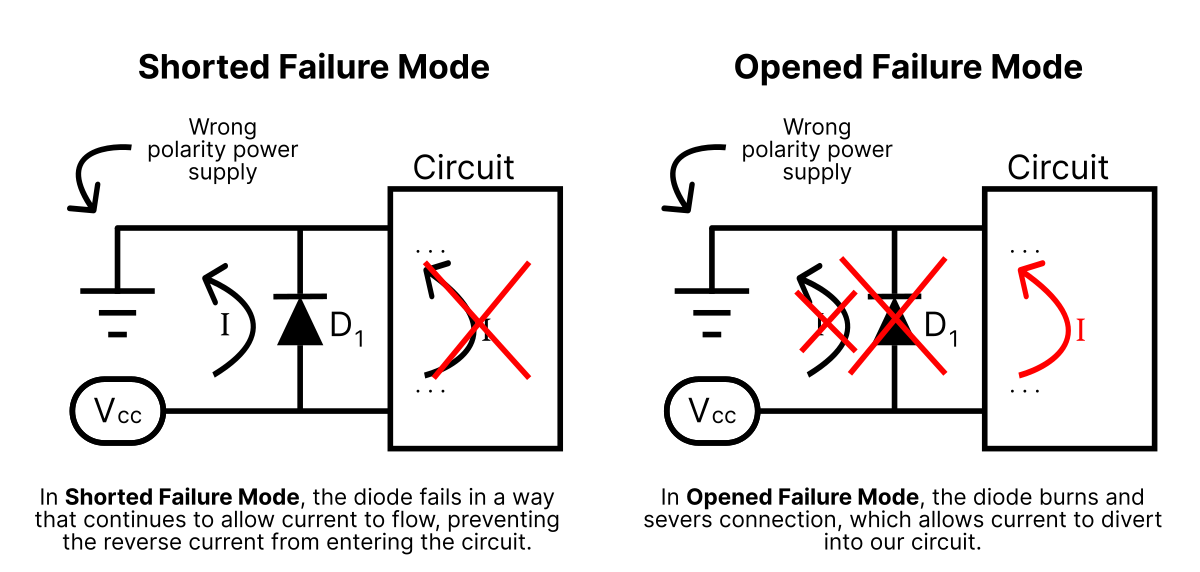
In practice on the repair bench, the most common presentation is: pedal comes in completely dead, correct polarity supply applied. Parallel protection diode has failed shorted. One diode replacement later, the pedal works perfectly. This failure mode is protective – the diode sacrificed itself. The less common open failure is the dangerous one.
The AC Supply Problem
The parallel diode has a specific failure scenario that the series diode does not: it performs poorly when an AC wall adapter is accidentally connected instead of a DC supply.
With AC input, the diode conducts on every negative half-cycle continuously. It isn’t briefly stressed – it dissipates power constantly as the AC alternates. The diode overheats rapidly. Depending on its failure mode, the circuit may then be exposed to the unprotected AC supply.
Do not rely on a parallel diode alone for protection against AC power input. If your design may encounter AC supplies – particularly in situations where pedals are powered by borrowed or unlabeled adapters – consider a series diode instead, or add a series resistor upstream of the parallel diode to limit fault current. A polyswitch (resettable fuse) in series with a parallel diode is another approach used in some commercial designs.
Part 5: Combination and Advanced Approaches
Series + Parallel Combination
Both configurations can be combined. Place a series diode in line with the supply, then add a parallel diode across the rails on the circuit side of the series diode.
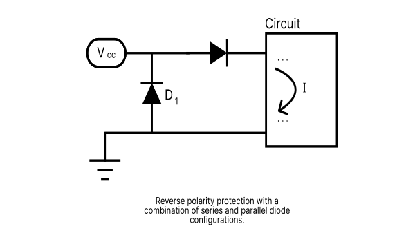
The series diode provides the primary protection – blocking reverse current before it reaches the circuit. The parallel diode adds the additional protection of shunting the reverse polarity current, ensuring that any residual current that happens to get by the series diode will have an easier, quicker option. In normal operation, the series diode’s forward drop is still present, and the parallel diode remains inactive.
This is overkill for most DIY builds, but reasonable for a design that will be used by others or in high-risk environments.
P-Channel MOSFET Protection
For applications where even the Schottky’s voltage drop is unacceptable, or where true blocking behavior without a sacrificial diode is required, a P-channel MOSFET can be used in the series position.
In correct polarity operation, the MOSFET turns on fully and the drain-source channel has a resistance of just a few milliohms – resulting in a voltage drop under 50mV at typical pedal current levels. Under reversed polarity, the MOSFET turns off completely and blocks current. No diode to fail. No voltage drop to speak of.
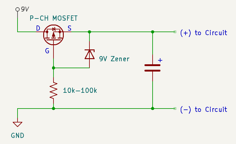
The complexity cost is real: correct MOSFET selection requires checking gate-source voltage limits and adding a Zener diode to protect the gate in higher-voltage applications. Through-hole P-channel MOSFETS (PFETs) in appropriate packages for DIY builds are less common than silicon or Schottky diodes, but the performance is measurably better.
R.G. Keen’s Advanced Power Switching and Polarity Protection article at Geofex covers the MOSFET approach in detail and is worth reading if this level of protection is relevant to your design.
Configuration Summary
| Configuration | Advantages | Limitations |
|---|---|---|
| Series (Silicon) | Voltage drop ~0.65V; full blocking; simple; no failure risk to circuit; single part | Reduced supply voltage |
| Series (Schottky) | Lower drop ~0.2-0.35V; true blocking; simple; single part | Lower reverse breakdown voltage (20V); slightly higher cost |
| Parallel (shunt) | No voltage drop in normal operation; simple, single part | Relies on diode surviving reverse event; fail-open risks circuit |
| Series + Parallel | Double protection; “belt-and-suspenders” | Voltage drop still present from series diode; two components |
| P-Channel MOSFET (PFET) | Near-zero voltage drop; true blocking; no sacrificial diode | More complex; harder to source in through-hole; higher cost |
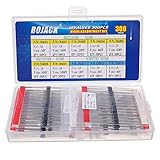
Parts List
| Part # | Description | Qty | Notes |
|---|---|---|---|
| 1N4001 | Silicon rectifier diode | 1 | Series or parallel. Standard protection. |
| 1N5817 | Schottky rectifier diode | 1 | Series. Lower forward drop (~0.2-0.35V). |
| 1N4007 | Silicon rectifier diode | 1 | Series or parallel. 1000V reverse rating – same as 1A current. |


References
[1] Geofex – A cheap and good polarity protector.
[2] Geofex – Advanced Power Switching (MOSFET approach)
[3] PFET for reverse voltage polarity protection
[4] Elliott Sound Products AN013 – Reverse Polarity Protection
[5] Two Mutts Audio Reverse Polarity Protection for guitar pedals
[6] 1N4001 Datasheet
[7] 1N5817 Datasheet
Guitar Effects Design in 48 Circuits or Less
This post is part of the 48 Circuits or Less series by Stompbox Electronics. Each installment covers one fundamental pedal circuit building block – concept, demonstration, and supplemental resources.
View more articles in this series here.
Meet the Author:

Hi, I’m Dominic. By day, I’m an engineer. By night, I repair and modify guitar effects! Since 2017, I’ve been independently modifying and repairing guitar effects and audio equipment under Mimmotronics Effects in Western New York. After coming out with a series of guitar effects development boards, I decided the next step is to support that community through content on what I’ve learned through the years. Writing about electronics gives me great joy, particularly because I love seeing what others do with the knowledge they gain about guitar effects and audio circuits. Feel free to reach out using the contact form!
The Tools I Use
As a member of Amazon Associates, Stompbox Electronics earns and is supported by qualifying purchases.


