

The BOSS compact pedal series was introduced in 1977, and with it came the ACA adapter power supply. BOSS introduced it’s modern power adapter, the PSA adapter, and has since moved on from the unregulated ACA equivalent.
As a result, guitarists purchasing these legacy BOSS pedals have found problems using the ACA-based pedals with the PSA adapter. This article will help answer your questions regarding the ACA power supply, as well as offer ways to deal with them.

As a member of the Reverb Partner Program, eBay Partner Network, and as an Amazon Associate, StompboxElectronics earns from, and is supported by, qualifying purchases.
Disclaimer: Stompbox Electronics and/or the author of this article is/are not responsible for any mishaps that occur as a result of applying this content.
What is a BOSS ACA Pedal?
A BOSS ACA pedal is one designed to use an ACA power adapter. In the late 70’s BOSS developed a power adapter called ACA. It was an unregulated 12V power supply for use with the BOSS compact pedal series.
When a power supply is unregulated, the voltage level drops as the demand for electrical current is increased. Most of the early BOSS pedals drew less than 10mA of current, so the voltage sag simply wasn’t an issue.
BOSS ACA Adapter Models
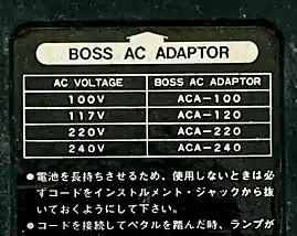
There were five models of the ACA adapter, depending on the mains voltage. They are:
- ACA-100 (Japan)
- ACA-120 (American)
- ACA-220 (China)
- ACA-230 (Europe, Israel, United Kingdom)
- ACA-240 (Australia)
There was a short time where BOSS offered a version of the ACA adapter that was designed to work with PSA pedals. That model was the ACA-120G, sold in America.
Does my BOSS Pedal Require an ACA Adapter?
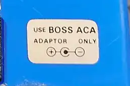
You can easily check to see if your BOSS pedal requires an ACA adapter. On most ACA pedals there is a sticker placed on the top-side of the pedal that says “Use BOSS ACA Adapter Only,” conveniently next to the power supply jack.
The ACA pedals have aged a bit, so there’s a good chance that sticker has fallen off. If that’s the case, there is usually a label on the backside of the pedal that shows a list of power supplies you could use. If there are model numbers starting with “ACA-___” then you have a BOSS ACA pedal on your hands. The “___” portion signifies the rest of the part number based on your country’s mains voltage. For the US, this is approximately ‘120’.
Can I Use a PSA Adapter with a BOSS ACA Pedal?
The short answer is no. If you decide to use a PSA adapter a couple things could happen. Most noticeably, the LED dimly illuminates when engaging the effect. In some cases, the LED may not illuminate at all. The effect won’t feel as strong as you would otherwise expect, either.
The ACA adapter provides unregulated 12 volts, while the PSA supplies a regulated 9 volts. BOSS pedals that are designed to be used with an ACA adapter have a circuit that lowers the 12 volts down to about 9 volts.
That also means that using a PSA adapter with an ACA pedal could cut the supply voltage to as low as 6 volts! This is why the effect will sound weak and the indicator LED will appear dim.
When Did BOSS Start Using PSA Adapters?
The BOSS PSA adapter is a regulated power supply that was released in 1983 with the BOSS DD-2. The DD-2 has a current draw of approximately 50mA, exceeding the current an ACA supply can handle.
In order to meet the new power requirements for modern effects, BOSS engineers designed the PSA adapter. For years BOSS used both adapters until 1997 when they discontinued ACA power supplies.
Can I Power a BOSS ACA Pedal with a Battery?
Yes. BOSS ACA pedals reduce the voltage it receives from an ACA adapter from 12V to approximately 9V. Therefore, the circuit itself expects 9 volts.
When you use a battery, that down-regulation does not occur, so normal 9V batteries will work just fine with BOSS ACA pedals.
The BOSS ACA Circuit Explained
Until the late 90’s the BOSS DS-1 required an ACA power adapter, so let’s use an old DS-1 as an example.
Below you’ll find part of the schematic for the second edition DS-1. Two components, labeled D3 and R38, connect in series between the power jack’s center pin (marked 10) and the input jack’s ring lug (marked 11). D3 is a switching diode (part number 1S2473) and R38 is a 470 ohm resistor.
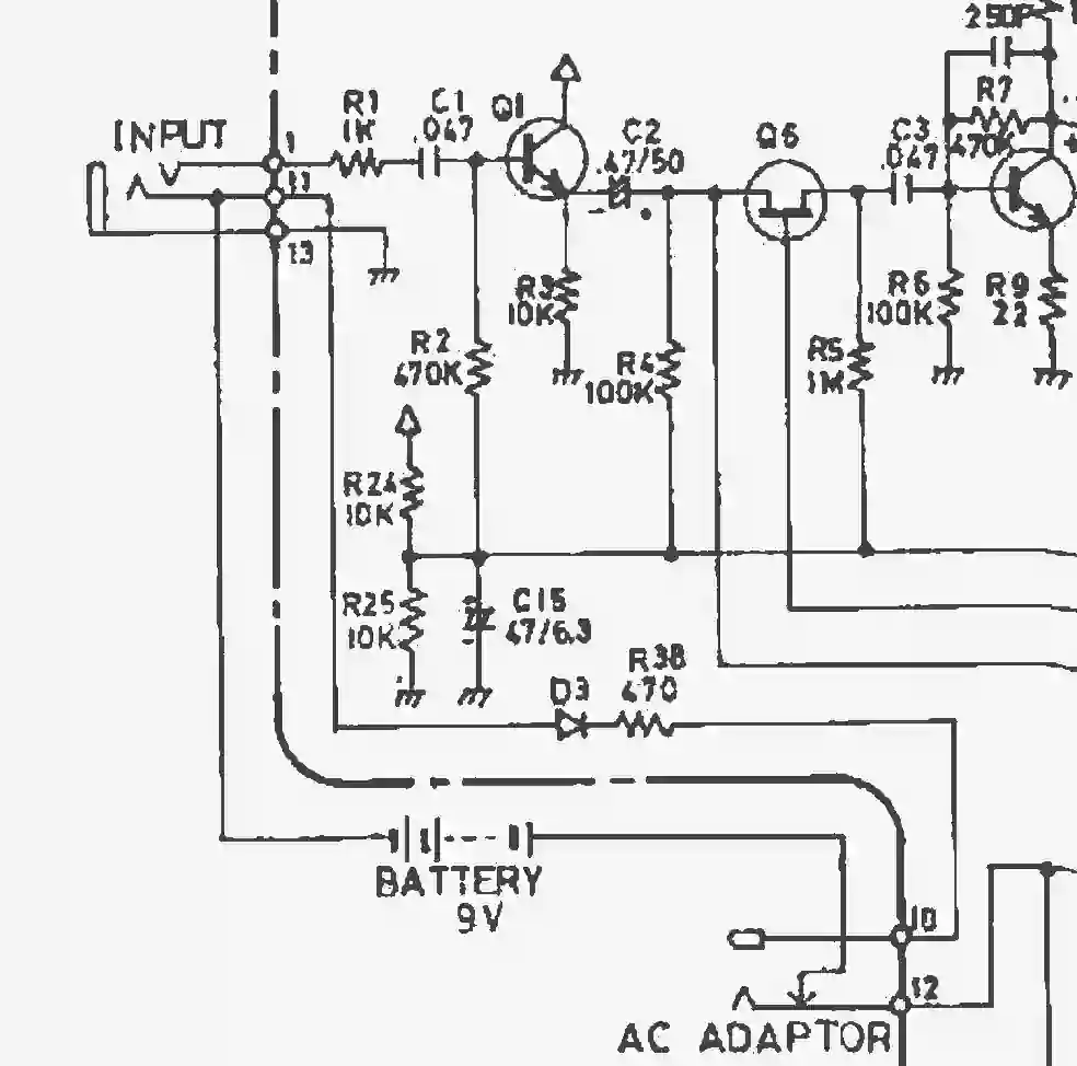
In this configuration, with a guitar jack plugged into the input, the common node of the circuit connects to D3 and R38 before reaching ground. The voltage drop across D3 and R38 mostly depends on the amount of current drawn by the guitar effect.
Modeling the ACA Circuit
The circuit is shown below, with the effect circuit modeled as a simple current source:
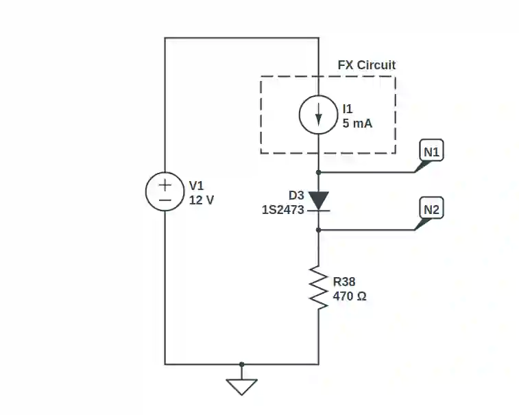
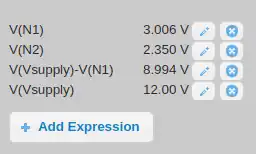
Let’s find the voltage drop across the FX Circuit. To do so, we need to select an expected current draw from the pedal. I chose 5mA since that is approximately the current draw for the DS-1.
The diode D3 has a forward voltage drop of 0.65 volts. The voltage drop across R38, with 5mA flowing through it, comes to (470 x 0.005 = ) 2.35 volts as per Ohm’s Law. Adding 2.35V to the diode drop gives us 3V. Finally, subtracting the D3+R38 voltage drop of 3V from the supply voltage of 12V gives us 9V.
It follows that lowering the current draw of the pedal has the effect of decreasing the voltage drop across R38, allowing more of the voltage drop to be available for the effects circuit. If the current draw of the pedal increases, then more voltage is dropped across R38 which diminishes the voltage available to the circuit.
The ACA circuit can also be seen as a form of reverse polarity protection. See Circuit 5 of 48: The Diode Protectors in the 48 Circuits or Less series for more information.
Alternatives to ACA Supplies
So now we know the downside of using a PSA supply with a BOSS ACA pedal. Is there a way around it? Yes!
1) Using a 12V Output
One method is to use a 12V supply instead of the standard 9V PSA supply. For example, the Voodoo Labs ISO 5 sports a 12V option that you could potentially use for a BOSS ACA pedal.
2) Daisy Chaining with other PSA Pedals
Another solution is to use a BOSS PSA adapter in conjunction with a daisy-chain cable. The PSA cable still supplies 9V, but using a daisy-chain cable ensures that the ground is common between all pedals in the chain.
Other PSA pedals internally connect the ring lug of the input jack and the negative lug of the power supply jack. Because all the pedals are daisy-chained, and since the sleeve connections are tied to common ground, the diode and resistor in the ACA circuit are effectively bypassed.
3) Modify the ACA Circuit to Accept PSA Adapters
A third solution is to modify the ACA circuit such that the diode and resistor are electrically bypassed. This involves removing the two components and soldering jumper wires in their place. The modification is simple and described below.
Modifying a BOSS ACA Pedal to Use PSA Adapters
You can modify your BOSS ACA pedal to accept a PSA adapter. The idea is to bypass the diode + resistor series arrangement altogether. The process is simple, and therefore a good modification for first-timers.
That said, if you don’t feel comfortable performing the modification you can always reach out to a local tech or send your pedal into a guitar pedal modification shop.
The ACA to PSA Conversion Mod
First, remove power from the pedal.
Second, locate the diode and resistor that forms the ACA circuit. The designations differ between each BOSS ACA model. I’ve compiled a list of BOSS ACA pedals and included the resistor/diode component designations.
Resistors and Diode Designations for BOSS ACA Pedals
| BOSS Model | Name | Diode Designator | Resistor Designator |
|---|---|---|---|
| BOSS BF-2 | Flanger | D10 | R64 – 56Ω |
| BOSS CE-2 | Chorus | D5 | R53 – 100Ω |
| BOSS CE-3 | Chorus Ensemble | D1 | R1 – 390Ω |
| BOSS CS-1 | Compression Sustainer | D4 | (None) – 470Ω |
| BOSS CS-2 | Compression Sustainer | D2 | R38 – 470Ω |
| BOSS CS-3 | Compression Sustainer | D10 | R32 – 220Ω |
| BOSS DF-2 | Super Feedbacker Distortion | D1 | R5 – 330Ω |
| BOSS DM-2 | Delay | D1 | R2 – 100Ω |
| BOSS DM-3 | Delay Machine | D1 | D3 – 180Ω |
| BOSS DS-1 | Distortion | D3 | R38 – 470Ω |
| BOSS GE-7/GE-7B | Equalizer / Bass Equalizer | D1 | R1 470Ω |
| BOSS FT-2 | Dynamic Filter | D2 | R4 180Ω |
| BOSS HF-2 | Hi Band Flanger | D10 | R64 – 56Ω |
| BOSS HM-2 | Heavy Metal | D1 | R2 – 330Ω |
| BOSS NF-1 | Noise Gate | D4 | (None) – 470Ω |
| BOSS OC-2 | Octave | D3 | R17 – 470Ω |
| BOSS OD-1 | Overdrive | D4 | R30 – 470Ω |
| BOSS OD-2 | Turbo Overdrive | D1 | R2 – 330Ω |
| BOSS PH-1r | Phaser | D6 | R56 – 100Ω |
| BOSS PH-2 | Super Phaser | D5 | R9 – 150Ω |
| BOSS SD-1 | Super Overdrive | D3 | R31 – 470Ω |
| BOSS SG-1 | Slow Gear | D4 | R38 – 470Ω |
| BOSS SP-1 | Spectrum | D4 | R30 – 470Ω |
| BOSS TW-1 | Touch Wah | D8 | R48 – 470Ω |
| BOSS VB-2 | Vibrato | D6 | R57 – 220Ω |
Now that you’ve located the correct components, remove both the resistor and the diode.
I usually heat up one of the solder joints and tilt the component up with a pair of insulated tweezers. Then, heat up the other joint and pull the component out using the same tweezers. Do this for both the resistor and diode.
Finally, solder jumper wires into the same solder holes that the diode and resistor had occupied. There are a couple options for what to use as jumper wires. Common options include normal 24AWG – 20AWG wire, or you can cut off the leads of a resistor that you aren’t using and use those.
Meet the Author:

Hi, I’m Dominic. By day, I’m an engineer. By night, I repair and modify guitar effects! Since 2017, I’ve been independently modifying and repairing guitar effects and audio equipment under Mimmotronics Effects in Western New York. After coming out with a series of guitar effects development boards, I decided the next step is to support that community through content on what I’ve learned through the years. Writing about electronics gives me great joy, particularly because I love seeing what others do with the knowledge they gain about guitar effects and audio circuits. Feel free to reach out using the contact form!
The Tools I Use
As a member of Amazon Associates, Stompbox Electronics earns and is supported by qualifying purchases.


