
As a member of the Reverb Partner Program and as an Amazon Associate, StompboxElectronics earns from, and is supported by, qualifying purchases.
Disclaimer: Stompbox Electronics and/or the author of this article is/are not responsible for any mishaps that occur as a result of applying this content.
What is a Charge Pump Inverter?
A charge pump is an integrated circuit (IC) that is used to convert from one voltage to another.
As an example, let’s say you want to build a circuit that runs on +18Vdc, but you want to power it using a +9Vdc adapter. You can use a charge pump IC to double the +9Vdc supply to yield +18Vdc.
Similarly, if you’d rather have -9Vdc, then you can create a charge pump circuit that converts +9Vdc into it’s inverted counter-part.
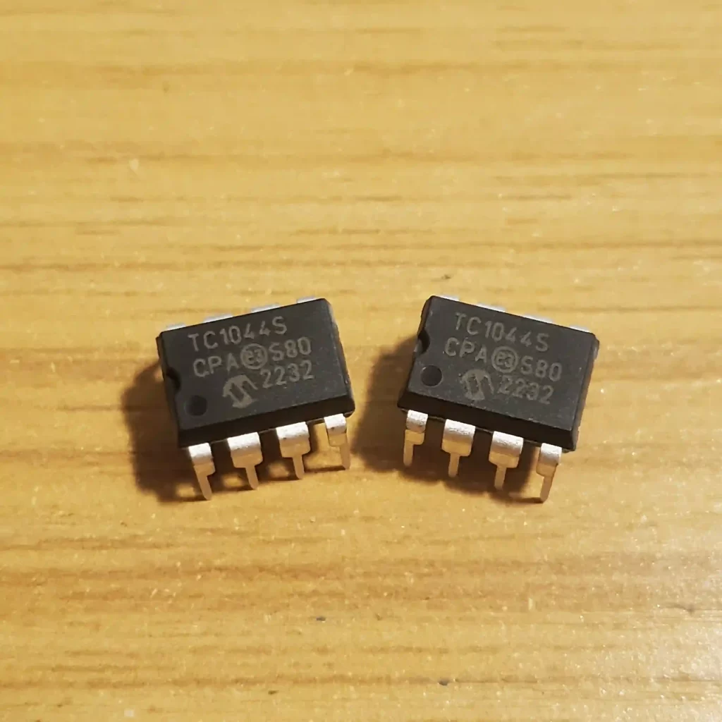
Charge pumps are usually purchased in the form of an integrated circuit. One example, and the focus of this article, is the TC1044S. The TC1044S is a DC-to-DC Voltage Converter manufactured by Microchip, and it’s very common in guitar pedal circuits for DC voltage conversion.
How does a charge pump work?
Charge pump ICs have a combination of internal micro-sized capacitors and electronic switches. The switches are toggled on and off at a constant frequency, and they are arranged such that the charge transfer characteristic between each of it’s internal capacitors is controlled and exploited.
Initially, capacitors are charged by the input voltage source (say, +9Vdc). The switches are then controlled to change their state, connecting the capacitors in a specific sequence. Switching the capacitor sequence results in charge transfer between neighboring capacitors, which works out to an inverted voltage at the output.
For more information, see Guide to Integrated Charge Pump DC-DC Conversion by Analog Devices.
Uses for Negative Supply Voltages
There are at least two uses for negative supply voltages in guitar effects pedals:
- Negative-Supply PNP Transistor circuits
- Dual-Supply Op Amp Circuits
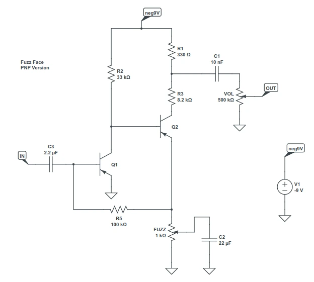
Firstly, PNP transistor-based circuits (the Fuzz Face for example) are often written utilizing negative supply voltages. The charge pump allows you to power your guitar pedal with a standard +9Vdc adapter and invert the supply voltage for the PNP circuit.
Second, op amp circuits can be either single-supply or dual-supply (also known as “split-rail“). Single-supply op amp circuits are powered using one voltage source, while dual-supply op amp circuits are powered with two voltage sources: one positive and one negative.

Charge Pump Characteristics
There are many charge pumps to choose from, and it helps to know how to differentiate one from another. To do so, you need to get familiar with the characteristics of charge pumps. Specifically:
- Maximum Voltage
- Switching Frequency
- Output Voltage vs. Output Current (Circuit Loading)
This article focuses on the TC1044S, so we will use it’s datasheet as the example.
Maximum Voltage
Charge pumps have a maximum voltage at which they are able to operate, which is specified in the Absolute Maximum Ratings section of the datasheet. For the TC1044S, the maximum voltage at which it can operate is 12Vdc. Attempting to operate the TC1044S with supply voltages over 12Vdc will damage the chip.
Here is a list of maximum voltage ratings for various charge pumps:
Common Maximum Voltage Ratings for Various Charge Pump ICs
| Device | Maximum Rated Voltage |
|---|---|
| TC1044S | 12V |
| LT1054 | 15V |
| TC962 | 18V |
| MAX1044 | 10V |
| ICL7660 | 10V |
Switching Frequency
Charge pumps operate at a default switching frequency specified by the manufacturer. The default switching frequency for the TC1044S is 10kHz. Generally, a lower switching frequency corresponds to a more efficient operation.
10kHz is pretty low for us guitar pedal enthusiasts. We’re operating in the audio band, which is generally considered any frequency between 20 Hz and 20kHz. A charge pump that inherently switches at 10kHz (like the TC1044S) will induce an audible whine in our circuit, making it unusable.
Luckily, charge pump manufacturers have included a BOOST option that allows us to increase the switching frequency to a level above the audio range. The tradeoff is a less efficient charge-pump, but this is generally OK for circuits pulling less than around 50mA.
Common Switching Frequencies for Various Charge Pump ICs
| Device | Default Switching Frequency | Boosted Switching Frequency |
|---|---|---|
| TC1044S | 10kHz | 45kHz |
| LT1054 | 25kHz | Max: 35kHz* |
| TC962 | 12kHz | 24kHz |
| MAX1044 | 5kHz | 30kHz** |
| ICL7660 | 10kHz | 60kHz** |
**The MAX1044/ICL7660 datasheet specifies the boosted frequency is 6x the default.
Output Voltage vs. Output Current (Circuit Loading)
The chart in Figure 9.4 shows the Output Voltage vs. Output Current of the TC1044S charge pump. Each line represents a given input supply voltage. The bottom-most line represents the case where the input voltage is +12V (the maximum possible supply voltage). The line above that is the case where the input voltage is +11V, etc.
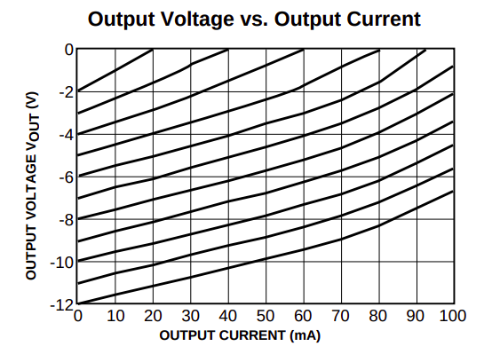
If there is no circuit connected to the charge pump, then the output current is 0mA. The plot tells us that, when the output current is 0mA, the output voltage will be an equal and negative version of the input voltage.
However, when we hook up a circuit, the load current increases and the absolute output voltage starts to diminish. This can become a bigger deal as the load current increases.
For example, if your circuit requires -9V, but the current draw is 80mA, then from this graph the voltage will be pulled all the way down to -5V! So, when working with charge pumps, it helps to know the expected current draw of your circuit.
Charge Pump Inverter Schematic
A basic charge pump inverter circuit is shown in Figure 9.5 using the TC1044SCPA. It involves 2 capacitors (C1 and C2) and is adapted from the Application Notes section in the TC1044S datasheet.
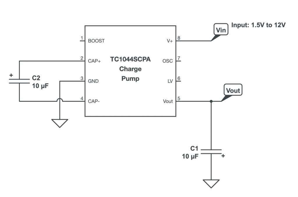
The capacitors must be electrolytic and the polarity of the configuration is very important. For C2, the positive lead is attached to pin 2 (CAP+). On the other hand, the negative lead of capacitor C1 connects to pin 5 (Vout).
According to the TC1044S datasheet, the input voltage can be anywhere from 1.5V to 12V, making it safe to use the standard 9Vdc voltage level commonly used in guitar pedal circuits.
Earlier, it was mentioned that charge pumps operate at a specific default frequency. For the TC1044S the default frequency is 10kHz. As a result, the circuit provided in Figure 9.5 produces an audible whine.
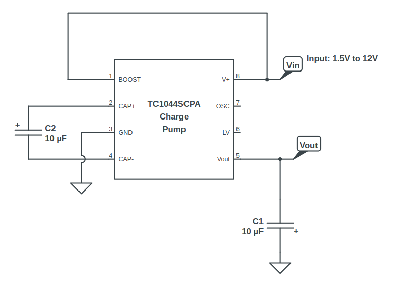
Luckily, Microchip engineered a BOOST option (pin 1) that increases the operating frequency from 10kHz to 45kHz, effectively moving it out of the audio range and eliminating the noise. To enable the BOOST option connect pin 1 to the input voltage (pin 8), as shown in Figure 9.6.
Charge Pump Inverter Parts List
Use the following parts to build the voltage inverter circuit shown above. Remember to stay at or below the maximum voltage rating of 12Vdc for the TC1044.
| Parts | Qty |
|---|---|
| TC1044SCPA | 1 |
| 10uF Electrolytic Capacitor | 2 |

TC1044S Alternatives
The TC1044S is a “pin-compatible upgrade” to the TC7660, according to the TC1044S datasheet. You can use these two chips interchangeably.
The Maxim Integrated MAX1044 and ICL7660 are pin-to-pin compatible with the TC1044. However, keep in mind that the maximum voltage for both MAX1044 and ICL7660 is 10V. I recommend going through their respective datasheets and comparing them with your requirements before committing to any replacements.
Alternatives that do not have pin-for-pin compatibility with the TC1044S include the Texas Instruments LT1054 and TC962. Always read the manufacturer’s datasheet before committing to these as potential alternatives.
Guitar Effects Design in 48 Circuits or Less
The 48 Circuits or Less article series serves to close the gap between DIY guitar effects design and guitarists interested in the craft by uniquely curating the most important aspects of DIY guitar effect circuit design. This post is part of the 48 Circuits or Less series. View more articles in this series here.
Meet the Author:

Hi, I’m Dominic. By day, I’m an engineer. By night, I repair and modify guitar effects! Since 2017, I’ve been independently modifying and repairing guitar effects and audio equipment under Mimmotronics Effects in Western New York. After coming out with a series of guitar effects development boards, I decided the next step is to support that community through content on what I’ve learned through the years. Writing about electronics gives me great joy, particularly because I love seeing what others do with the knowledge they gain about guitar effects and audio circuits. Feel free to reach out using the contact form!
The Tools I Use
As a member of Amazon Associates, Stompbox Electronics earns and is supported by qualifying purchases.


