
Cut-Off Frequency:
RC Low-Pass Filter Interactive Calculator
This tool allows you to visualize the frequency response of a first-order passive RC low-pass filter. It shows the magnitude response in decibels (dB) versus the frequency in Hertz (Hz) passing through the filter.
A vertical line designates the filter's cut-off frequency at wherever the magnitude cuts through -3dB. If that frequency happens to be outside the audio band (20 - 20kHz) then the line will be out of view by default.
How to use the RC Low-Pass Filter Interactive Tool
There are two slider controls, one for the resistance value and one for the capacitance value. Swipe the slider to the left or right to change the capacitance or resistance value.
The range of each slider control is based on unit prefixes. For capacitance, select uF, nF or pF. For resistance, you have ohms, kOhms, and MOhms.
The plot should automatically update when you:
- choose a different unit prefix range, or
- change the value with the slider control.
The cut-off frequency, or -3dB frequency, is updated along with the chart.
RC Low-Pass Filter Calculations
There are only 2 calculations involved in this tool: the cut-off frequency and the magnitude/frequency response in dB.
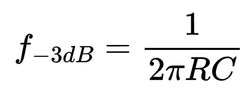
Cut-Off Frequency
For computing the cut-off frequency, the tool uses the following equation:
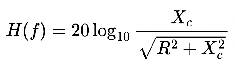
Magnitude/Frequency Response
To calculate the magnitude/frequency response of the low-pass RC filter, the tool uses the following equation (derived below):
Passive RC Filter Transfer Function Derivation
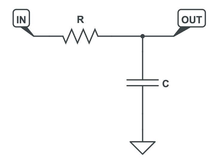
You can construct an RC low-pass filter using just two components: a resistor and a capacitor. The input is fed into the resistor, and the output is taken between the resistor and capacitor. This resembles a voltage divider, just with a capacitor in the place of "R2".
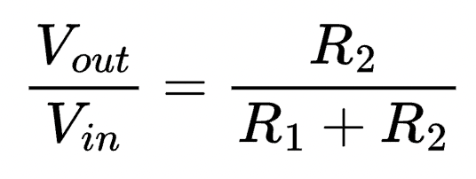
So, we can probably get away with using an equation that's similar to the standard voltage divider circuit. As a reminder, here's the voltage divider equation:

Modifying this slightly gives us a ratio of output to input (which is the mathematical definition of transfer function):
Of course, we don't have two resistors. Instead, R2 is replaced with a capacitor C. That means we need to shift our equation from using resistance values to using impedance values.
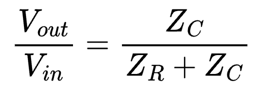
Impedance is the effective resistance of an electrical circuit, denoted using the letter Z. The top of this equation is asking for the impedance of only the capacitor (Zc). The bottom part of the equation asks for the impedance when the resistor is in series with the capacitor (Zr + Zc).
Impedance and Reactance of a Capacitor
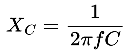
The impedance of a capacitor is usually expressed as an imaginary number and involves the calculation of capacitive reactance (Xc). Wikipedia defines capacitive reactance as a quantity that describes the "opposition to the change of voltage" across the capacitor.
The impedance, Zc, of a capacitor is expressed as:
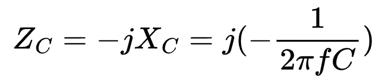
From the equation above, a capacitor has frequency-dependent reactance and impedance. So it's ability to "oppose" changes in voltage varies with the frequency of the voltage signal across it.
Impedance of a Resistor
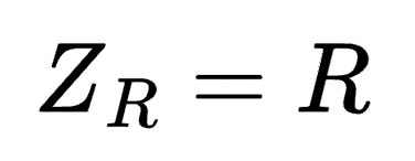
The impedance of a resistor is simply the resistor's resistance value. There's no frequency-dependence involved with resistive impedance:
Impedance of a Resistor and Capacitor in Series
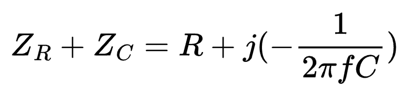
At this point we have the impedance for a resistor (ZR) and the impedance of a capacitor (ZC). The impedance of a resistor and capacitor in series is:
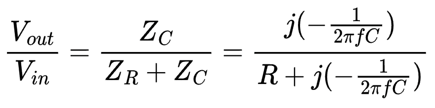
Transfer Function of the Passive RC Low-Pass Filter
Based on the above, the transfer function of a passive first-order RC low-pass filter is:
For us, the transfer function written like this isn't very useful. Instead, we want to know the magnitude of the transfer function. That will give us the actual ratio without having to deal with imaginary numbers.
Mathematically, this means we need to convert the cartesian form (a + jb) of the complex numbers to their magnitude-phase form. Read more on the process.
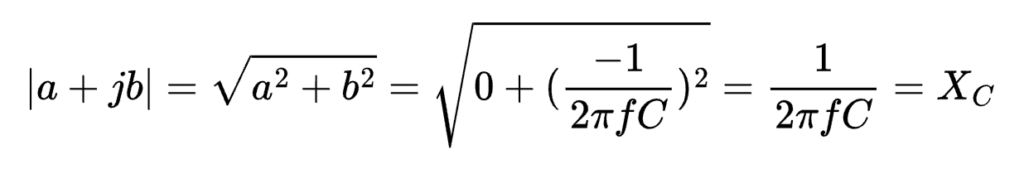
For the numerator, the cartesian form can be rewritten as:
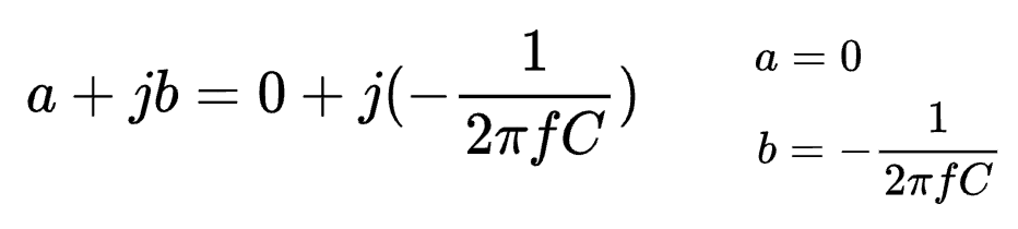
And the magnitude of the numerator is the square-root of the sum of the squares of a and b. In this case, it ends up equating to the reactance of the capacitor:
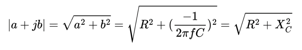
For the denominator, the cartesian form is:
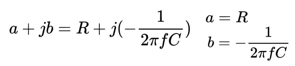
The magnitude of the denominator is therefore the sum of the squares of the resistance and reactance:
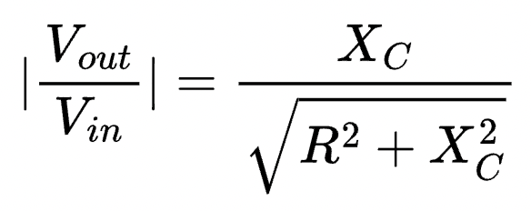
Magnitude of the RC Low-Pass Transfer Function
Put everything together, we have the following equation for the magnitude of the RC low-pass transfer function:
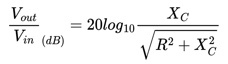
Converting to Decibels
The tool calculates the magnitude of the RC low-pass transfer function using the equation above. Then, it converts that value to the more conventional decibel scale using the following equation:
Meet the Author:

Hi, I'm Dominic. By day, I'm an engineer. By night, I repair and modify guitar effects! Since 2017, I've been independently modifying and repairing guitar effects and audio equipment under Mimmotronics Effects in Western New York. After coming out with a series of guitar effects development boards, I decided the next step is to support that community through content on what I've learned through the years. Writing about electronics gives me great joy, particularly because I love seeing what others do with the knowledge they gain about guitar effects and audio circuits. Feel free to reach out using the contact form!