[Last Updated: January 6, 2024]
As a member of the Reverb Partner Program and as an Amazon Associate, StompboxElectronics earns from, and is supported by, qualifying purchases.
Disclaimer: Stompbox Electronics and/or the author of this article is/are not responsible for any mishaps that occur as a result of applying this content.
Intro to The Voltage Divider
The voltage divider is one of the most common circuits you will run into when designing guitar effects. You may hear terms like:
- Reference Voltage
- Bias Voltage
- DC Bias Point
- DC Operating Point
All these terms more or less point to the same thing: the generation of a constant voltage. The voltage divider allows you to derive a fraction of an input voltage, making it perfect for generating reference and bias voltages.
The Need for a Bias Voltage
So why might we need a constant bias voltage? Let’s start by taking a look at Figure 3.1. It’s a sine wave, but imagine it’s your guitar signal.
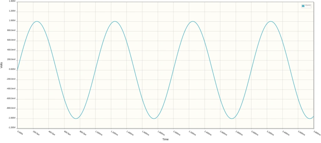
Notice that the signal is traveling above and below 0V. The max upward swing reaches +1V, while the downward swing hits –1V. The signal is said to be centered at 0V.
The Supply Voltage
The typical range of voltages you might see in a guitar circuit ranges from 0V (ground) up to the supply voltage. The supply voltage is the voltage with which you power your circuit. In our example, it’s 9V.
There’s one problem: our guitar signal in Figure 3.1 travels into negative voltage territory. If we try to use the guitar signal as-is, our circuit won’t be able to process the negative voltage values because they are out of the supply voltage range (0 to +9V). The signal might look something like Figure 3.2, with the negative voltage swing clipped off:
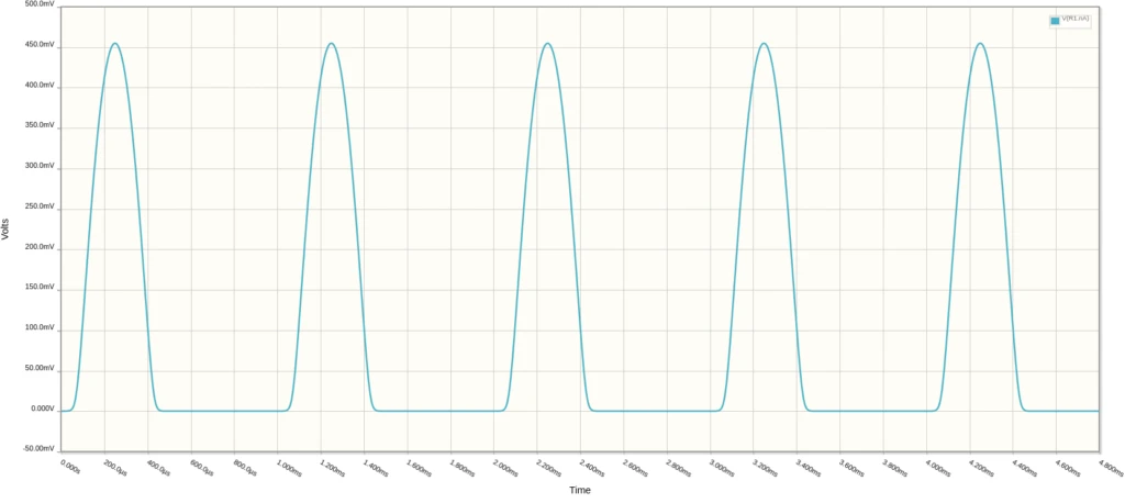
So half of our face-melting signal is lost because our guitar pedal can’t understand negative voltages. We have two solutions:
- Force our circuit to understand negative voltages by using a dual-supply power source.
- Force the signal into positive voltage territory and use a single-supply power source.
In this case, we’ll focus on the second solution: force the signal into positive voltage territory.
Biasing The Guitar Signal
Let’s work with what our power supply has to offer: positive voltages. To adapt ourselves, we need to force our guitar signal upwards on the graph so the upward and downward swings are all contained in positive voltage territory.
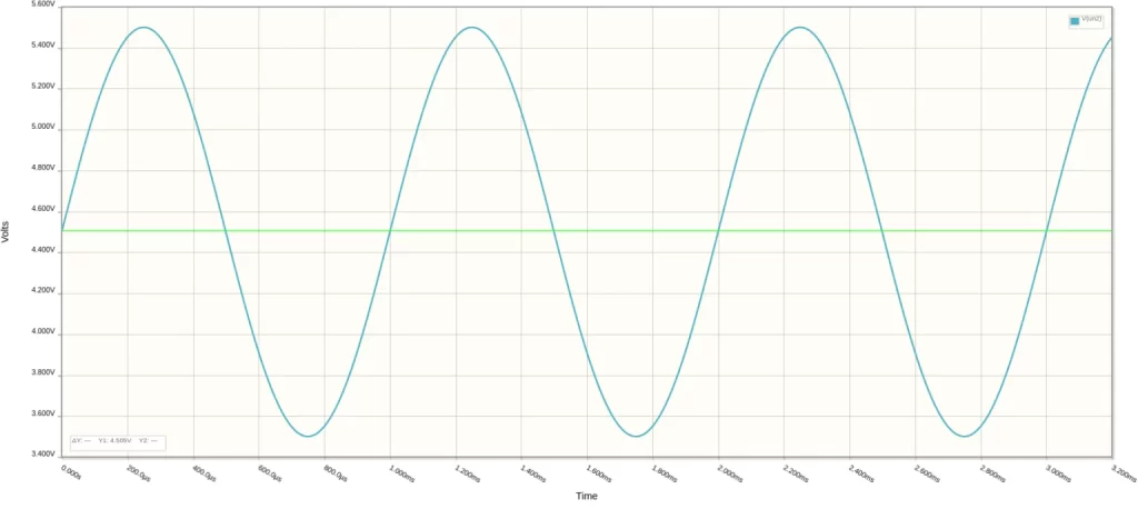
The process of shifting an entire signal up or down is called biasing. It involves superimposing an AC signal on top of a constant DC voltage. The time-varying component will be centered around the DC voltage.
A common rule is to bias the guitar signal at half the supply voltage. In our example, the supply voltage is 9V so the DC bias should be 9V / 2 = 4.5V. See Figure 3.3 for what the signal looks like after biasing.
The Voltage Divider Circuit
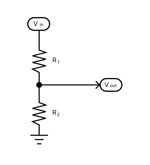
You can generate bias voltages using the voltage divider circuit. It’s one of the easiest circuits to build, using just two resistors. The input voltage, labeled Vin, is applied across two resistors, R1 and R2. The output voltage is measured across the R2 resistor and ground.
Voltage Divider Equation
Using the voltage divider equation in Equation 3.1 you can calculate the output voltage (Vout) from knowing R1, R2, and Vin.

Note that if we use the same resistor value for R1 and R2 the output voltage is half the input voltage. For example, a voltage divider built with two 10kΩ resistors and fed with 9V supply voltage will generate 4.5V.
For voltages other than half the supply voltage it can be tricky to choose resistor values. You’ll have to do some trial and error to find the resistor values that work for you. In that case, you can use a voltage divider calculator to help you work out resistor values if you need to bias to a different voltage.
Choosing Resistors for our Voltage Divider
In our biasing example, Vin is the supply voltage of 9V and Vout needs to be 4.5V. R1 needs to be equal to R2 for this to happen but which value should we pick?
Usually, a resistance between 10k and 47k works just fine. If you would like a more in-depth look at how to choose R1 and R2 see R.G. Keen’s article on Geofex.
Voltage Divider Exercise
For this exercise, you should build the voltage divider circuit in Figure 3.4 with different resistor values and see what you get. See the parts list below for what you’ll need to complete this exercise.
For example, try 10kΩ and 47kΩ for R1 and R2, respectively, and measure the output voltage. Then swap them and measure again. Afterward, use both 47kΩ resistors as R1 and R2, and measure the output voltage. Then do the same with two 10kΩ resistors.
Voltage Divider Parts List
The following list covers the parts you’ll need to fully understand the voltage dividier circuit. Follow the exercise above with a breadboard to learn more about the voltage divider circuit.
| Parts | Qty |
|---|---|
| 10kΩ Resistor | 2 |
| 47kΩ Resistor | 2 |
Using the Reference Voltage Generator on the PROTIS 1
The PROTIS 1 Development Board comes with an embedded reference voltage generator circuit. In fact, it uses a voltage divider circuit as part of its design. The reference generator circuit, labeled REFERENCE SELECT, is located on the right side of the board.
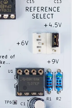
There are three (3) reference voltage options you can select using the provided jumpers: +9V, +6V, and +4.5V.
Choose the 4.5V option if your effects circuit is being powered by 9V. Likewise, choose 6V if the circuit is powered by 12V, and choose 9V if the circuit is powered by 18V.
You can access the reference voltage generator output via the header labeled REFERENCE along the right side of the breadboard prototyping area. Use a male-to-male jumper cable, provided as an option with the PROTIS 1.
Resources
[1] Iota Pedals – Voltage Divider Basics, (C)2020-2021
[2] Stompbox Electronics Voltage Divider Calculator
Guitar Effects Design in 48 Circuits or Less
The 48 Circuits or Less article series serves to close the gap between DIY guitar effects design and guitarists interested in the craft by uniquely curating the most important aspects of DIY guitar effect circuit design. This post is part of the 48 Circuits or Less series. View more articles in this series here.
Meet the Author:

Hi, I’m Dominic. By day, I’m an engineer. By night, I repair and modify guitar effects! Since 2017, I’ve been independently modifying and repairing guitar effects and audio equipment under Mimmotronics Effects in Western New York. After coming out with a series of guitar effects development boards, I decided the next step is to support that community through content on what I’ve learned through the years. Writing about electronics gives me great joy, particularly because I love seeing what others do with the knowledge they gain about guitar effects and audio circuits. Feel free to reach out using the contact form!
The Tools I Use
As a member of Amazon Associates, Stompbox Electronics earns and is supported by qualifying purchases.


