
Component Values
Resistor R:
Capacitor C:
Supply Voltage Vcc (V):
Upper Threshold (V):
Lower Threshold (V):
Design Parameters
Oscillation Frequency:
Period (T):
High Pulse Width (%):
Low Pulse Width (%):
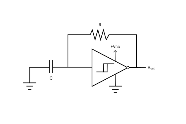
The Schmitt Trigger Oscillator Calculator
This schmitt trigger oscillator calculator allows you to calculate component values based on a desired oscillation frequency and threshold voltage range. You also have the option to plug and play with different resistor and capacitor values, to fine tune the design.
Using the Schmitt Trigger Oscillator Calculator
No Method: Plug and Play
Choose "None" in the Method dropdown to select "Plug and Play" mode. This mode calculates all design parameters based on component values (R and C) and the Supply Voltage.
If the 50% Duty Cycle? dropdown is set to "Yes" then the tool assumes 50% duty cycle and the threshold voltages are calculated automatically with the Calculate button. The high threshold voltage level is 2/3 supply voltage, while the low threshold voltage level is 1/3 supply voltage.
Selecting "No" in the 50% Duty Cycle dropdown enables the voltage threshold input fields, allowing you to enter voltage levels for your specific device. Here is a list of typical values for common Schmitt Trigger ICs (assuming specific supply voltages):
| Device Name/MFR | Supply Voltage (Vcc) | Positive-Going Threshold | Negative-Going Threshold |
|---|---|---|---|
| Texas Instruments SN74AHC14 | 5.5V | 3V | 2.5V |
| Texas Instruments CD40106 at 5V | 5V | 2.9V | 1.9V |
| Texas Instruments CD40106 at 10V | 10V | 5.9V | 3.9V |
| NXP HEF4093B | 10V | 5.2V | 4.2V |
Method 1: Solve for R
With the Solve for R method, the required value fields appear in light green. After filling in the values for the fields, click Calculate to calculate a resistance R.
The 50% Duty Cycle? dropdown works the same as above. Choose "No" to enter device-specific voltage thresholds. Choose "Yes" to assume 50% duty cycle, from which the voltage thresholds will be automatically calculated.
In the Period/Frequency dropdown list, choose "Frequency" to specify a particular oscillation frequency to design for. Likewise, choose "Period" to design for a specific period.
Method 2: Solve for C
The "Solve for C" method works the same way as "Solve for R" except the tool will be calculating the capacitance value C. The required parameters light up in green, simply fill those out and hit Calculate. The dropdowns work the same way as in Method 1.
The Schmitt Trigger Oscillator Equations
All equations are adapted from this article on All About Circuits.
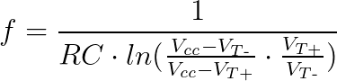
Frequency of Oscillation
The calculator uses the following equation to calculate the frequency of oscillation.
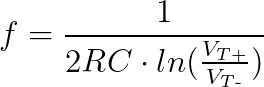
If the 50% Duty Cycle option is selected, then the equation simplifies to:
Period of Oscillation
The period of oscillation is just the inverse of the frequency value, T = 1/f.
Duty Cycle
The duty cycle can be seen as the percent of time the output stays high relative to the entire period. For example, a duty cycle of 20% means that the output stays high for 20% of the period and goes low for 80% of the period. If the period is 1 second, then in this scenario the output stays on for 200ms, then off for 800ms, then on for 200ms, etc.
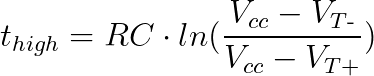
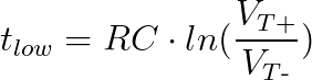
The equation for the high pulse width is
The equation for the low pulse width is
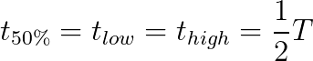
If the duty cycle is set to 50% then the high and low pulse widths are equal to half the period.
Rules for Resistor Values
The tool only allows an integer or decimal value into the resistance fields. It doesn't understand characters like 'k' or 'M', so use the drop-down box on the side of each input box to convert the value to kilo ohms or mega ohms.
Rules for Capacitance Values
Like resistor values, the tool doesn't understand characters like 'p', 'n', 'u', or 'm'. So, use the drop-down box on the side of each input box to convert the value to pico, nano, micro, or milli Farads.
Rules for Voltage Values
The tool only recognizes real numbers for voltage values and does not convert unit suffixes. For example, for 10mV simply write “0.010” into the field.
For the threshold values, neither threshold level should exceed the supply voltage. The lower threshold cannot exceed the upper threshold. The lower threshold cannot be zero.
Rules for Design Parameter Values
The tool only allows an integer or decimal value into the design parameter fields. For the oscillator frequency's units, choose Hz, kHz, MHz, or GHz using the dropdown box beside the oscillator frequency field.
Likewise, for the period units choose ns, us, ms, or s using the dropdown box.
Meet the Author:

Hi, I'm Dominic. By day, I'm an engineer. By night, I repair and modify guitar effects! Since 2017, I've been independently modifying and repairing guitar effects and audio equipment under Mimmotronics Effects in Western New York. After coming out with a series of guitar effects development boards, I decided the next step is to support that community through content on what I've learned through the years. Writing about electronics gives me great joy, particularly because I love seeing what others do with the knowledge they gain about guitar effects and audio circuits. Feel free to reach out using the contact form!