
Component Values
Resistor R1:
Resistor R2:
Resistor R3:
Resistor R4:
Capacitor C1:
Capacitor C2:
Design Parameters
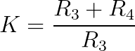
Gain (K):
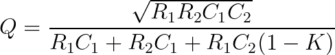
Quality Factor (Q):
Center Frequency (Fc):
Scale Factor (FSF):
m:
n:
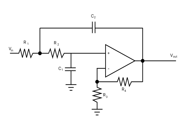
The Low-Pass Sallen-Key Filter Calculator
The Sallen-Key Filter is a second-order (two-pole) filter topology used to implement active filtering. The design equations are straightforward and simple to use, as long as you know the parameters for which you are designing. This Sallen-Key filter calculator is an attempt to make that process easier.
The calculator above allows you to design a Sallen-Key filter in four different methods, described below. Each method’s calculation depends on combinations of different known component values and expected design parameters. All calculations are based on a September 2002 Application Report from Texas Instruments, written by Jim Karki, document number SLOA049B.
The Transfer Function
A transfer function describes the relationship between the output of the filter to the input of the filter.
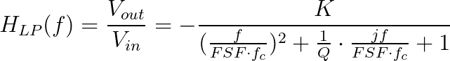
where K is the filter gain, f is the frequency variable, H denotes the transfer function, FSF is a frequency scaling factor, fc is the cutoff frequency, and Q is the quality factor of the filter.
The filter “works” in three general regions of operation: (1) when the frequency f is below the cutoff fc, (2) when the frequency f is at the cutoff fc, and (3) when the frequency f is above the cutoff fc.
- f << fc
- H(f) is approximately -K, so the output is simply the input multiplied by a gain factor of K.
- f/fc = FSF
- H(f) = -jKQ, the input signal becomes shifted in phase by 90 degrees (-j) and is additionally scaled by the Q factor.
- f >> fc
- H(f) is approximately -K*((FSF x fc)/f)^2, the input signal is shifted 180 degrees (negative) and is additionally attenuated by the frequency ratio squared.
Design Equations
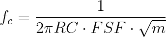
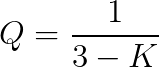
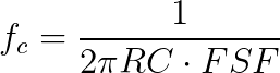
The following design equations are used for calculating filter gain (K), quality factor (Q), and scaled center frequency (FSF * fc).
Methods of Calculating Sallen-Key Filter Component Values
The tool lets you choose between four methods of calculation.
The first method is a plug-and-play style calculator. You simply plug in resistor and capacitor values, hit Calculate, and it spits out the answer. There is no simplification process, so I named it “None.”
The second, third and fourth methods simplify the calculation process, as described in Appendix A of TI’s application note. I labeled these methods 1, 2, and 3 respectively.
Method #1 – Set Filter Components as Ratios with Unity Gain
This method involves designing the filter such that there is no gain in the pass-band. Follow these steps:
- Firstly, assume K = 1. R4 becomes zero (just a wire) and R3 is non-existent.
- Choose a quality factor Q.
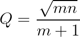
- Then, choose m to be a number between 0 and 1. (n is calculated for the desired Q factor, from equation 1.1)
- Choose a capacitance C for C1. (C2 will be calculated for you from the resulting n, equation 1.2).
- Note that C1 = C and C2 = n*C
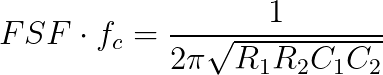
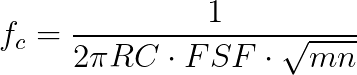
- Finally, choose FSF and center frequency fc. R will be calculated from equation 1.3.
- Note that R1 = m*R and R2 = R, equation 1.4.


Method #2 – Set Resistors as Ratios and Capacitors Equal
Here, you calculate the component values starting from a desired gain and quality factor. With the capacitor values held equal, the resistor values can be calculated by choosing the desired center frequency.
- Firstly, choose the desired gain, K.
- Then, choose the desired quality factor Q.
- The tool will alter the factor m to match the desired quality factor based on equation 2.1.
- Choose your capacitance value, C.
- Note that C1 = C2 = C, as in equation 2.2.
- Choose the center frequency, fc, and the scaling factor FSF. R is calculated from equation 2.3.
- Note that R1 = mR and R2 = R, as in eqution 2.4.
- Lastly, choose a resistance for R3. R4 is calculated based on R3 and K, from design equation 1.


Method #3 – Set All Filter Component Values Equal
This final simplication method assumes that all resistors have the same value and all capacitors have the same value. This method starts you off by selecting the quality factor, capacitance values, and center frequency. Finally, tool calculates the gain K and resistances R3 and R4.
- Firstly, choose the desired quality factor Q.
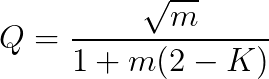
- The gain is calculated from equation 3.1.
- Second, choose a capacitance value, C. Note that C1 = C2 = C, as in equation 3.2.
- Choose a center frequency fc and scaling factor FSF.
- Resistance R is calculated from equation 3.3.
- Finally, choose R3.
- R4 is calculated from K and R3 in design equation 1.
Rules for Resistor Values
The tool only allows an integer or decimal value into the resistance fields. It doesn’t understand characters like ‘k’ or ‘M’, so use the drop-down box on the side of each input box to convert the value to kilo ohms or mega ohms.
Rules for Capacitance Values
Like resistor values, the tool doesn’t understand characters like ‘p’, ‘n’, ‘u’, or ‘m’. So, use the drop-down box on the side of each input box to convert the value to pico, nano, micro, or milli Farads.
Rules for Design Parameter Values
The tool only allows an integer or decimal value into the design parameter fields. For the center frequency’s units, choose Hz, kHz, MHz, or GHz using the dropdown box beside the center frequency field.
Meet the Author:

Hi, I’m Dominic. By day, I’m an engineer. By night, I repair and modify guitar effects! Since 2017, I’ve been independently modifying and repairing guitar effects and audio equipment under Mimmotronics Effects in Western New York. After coming out with a series of guitar effects development boards, I decided the next step is to support that community through content on what I’ve learned through the years. Writing about electronics gives me great joy, particularly because I love seeing what others do with the knowledge they gain about guitar effects and audio circuits. Feel free to reach out using the contact form!