
Resistor R1:
Resistor R2:
Resistor R3:
Resistor R4:
Supply Voltage Vcc (V):
Base-Emitter Voltage (V):
Beta/hFE:
Voltages
Collector Voltage Vc:
Base Voltage Vb:
Emitter Voltage Ve:
Currents
Collector Current Ic:
Base Current Ib:
Emitter Current Ie:
Gain (Av):
Using the Common-Emitter Amplifier Calculator
This tool was built to more easily determine the DC voltage and current values in a common-emitter amplifier circuit. The tool computes it’s output based on the calculation described below.
To use the calculator, input the resistance values for R1, R2, R3, and R4. Then specify the supply voltage (Vcc), the assumed base-emitter voltage (Vbe), and the assumed beta/hFE value of the transistor at-hand. Once all those values are specified, hit calculate to compute the DC voltage and current values for the base, emitter, and collector terminals.
Default Component Values
The default component values and voltages are those used in the original Electro-Harmonix LPB-1 circuit.
Changing Units
To change the display units, click on the field’s associated dropdown. Each resistance field has three prefixed units to choose from: normal ohms, kilo-ohms, and mega-ohms. Each voltage field has volts, millivolts, and microvolts available as display units. Likewise, each current field has amps, milli-amps, micro-amps, and nano-amps to choose from.
The default number of decimal places is 2 when calculating values. When changing the units, that number increases to 5 decimal places in order to retain the value’s resolution.
Calculating Common-Emitter Amplifier Values
Before going into the calculations there are some mathematical relationships you’ll need to know about. They are all observational in nature and a result of applying basic circuit analysis techniques (like KVL, KCL, Ohm’s Law, transistor properties, etc).
The second section will go into a more in-depth analysis and will reference all the relationships in this first section. The goal is to build a system of equations that we can solve with simple algebraic substitution.
The third section calculates all the DC values of the Common-Emitter Amplifier circuit using the system of equations we derive in section 2.
Section 1: Mathematical Relationships
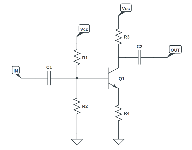
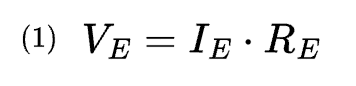
The emitter terminal voltage VE is the voltage drop across the emitter resistor. In the schematic, the emitter resistor is labelled R4, but here it is specified by RE.
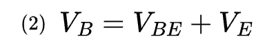
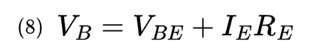
The base terminal voltage VB is the emitter voltage plus the voltage drop across the base-emitter junction. Usually that drop is specified as 0.65V or 0.7V. Here, we’ll simply use VBE and remember that it’s a constant value.
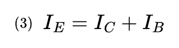
All currents flowing into an electrical device must equal the sum of currents flowing out of the device. So the current flowing out of the emitter terminal must equal the sum of currents flowing into the base and collector terminals.
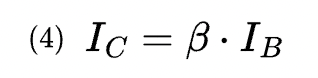
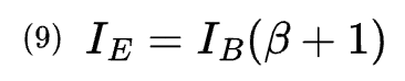
A transistor’s β value (or hFE) is specified as the current gain between the collector and base. That is, the collector current is a magnification of the base current by a factor of β.
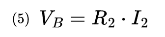
The voltage at the base terminal is equal to the voltage drop across R2.
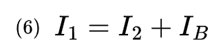
For (3) we used the fact that the current flowing into a device equals all the currents flowing out of it. That works for nodes in a circuit as well. Therefore, focusing on the voltage divider, the current flowing through R1 is equal to the current flowing through R2 plus the current flowing into the base terminal of the transistor.
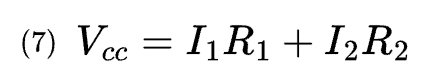
One last observation involves a KVL (Kirchoff’s Voltage Law) loop analysis on the voltage divider. The supply voltage is equal to the voltage drop across R1 plus the voltage drop across R2.
Section 2: Common-Emitter Analysis
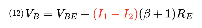
Let’s replace the emitter voltage in equation (2) with the expression from (1) to get a new equation for the base voltage VB:
Next, we’ll substitute the expression for the collector current in (4) into (3) and simplify for a new expression that relates the emitter current IE to base current IB:
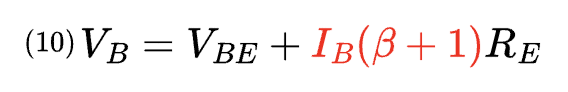
So now we have an expresison for the emitter current. Let’s insert that into the base voltage equation (8):
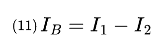
We can express the base current in terms of the currents in the voltage divider circuit, I1 and I2, through equation (6).
Substituting (11) into (10) gives us:
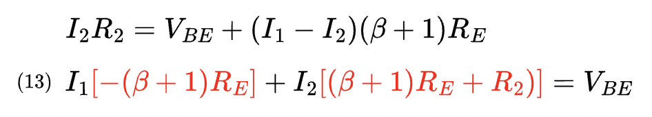
Equation (5) expresses the base voltage in terms of I2. Let’s set (5) equal to (12). Then, group terms around I1 and I2. Finally, arrange the equation so the constant value VBE is alone on one side of the equals sign.
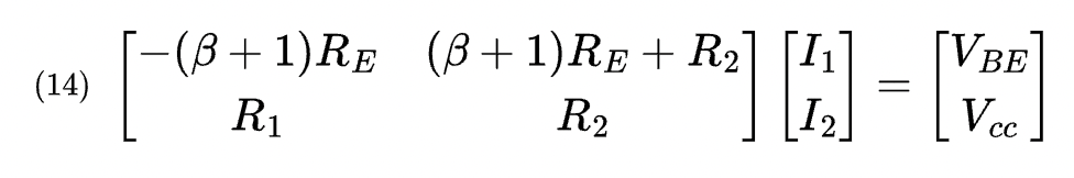
Lines (13) and (7) form a system of two linear equations with two variables (I1 and I2). They can be solved relatively easily by substitution. Here, they are both expressed in matrix form:
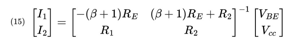
Multiplying each side by the inverse of the 2×2 matrix gives the following equation:
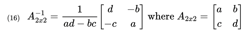
The inverse of a 2×2 matrix is simply another 2×2 matrix and is calculated using the following generic template:
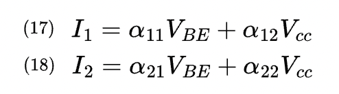
The final equations for the currents I1 and I2 are:
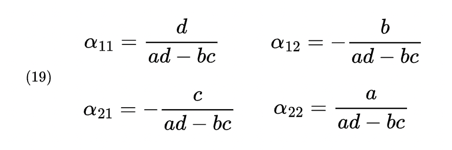
In (17) and (18) some constants were introduced to make things easy on the eyes. Those alpha values are calculated as follows:
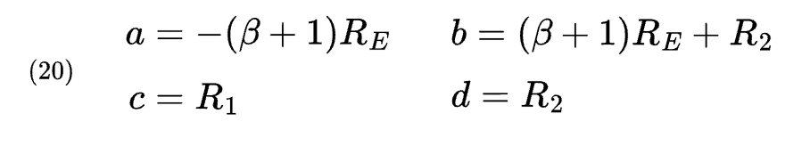
Remember those a, b, c, and d values all correspond to the matrix equation in (14):
Section 3: Finding the DC Values
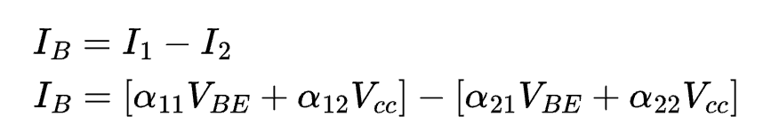
To calculate the base current, use the following:
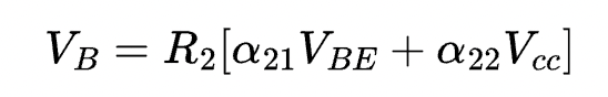
Find the voltage at the base terminal by substituting I2 in equation (5):
Finding the emitter voltage is fairly simple, just subtract the base-emitter voltage from the base voltage: VE = VB – VBE. It’s equally as simple to figure out the emitter current, which by Ohm’s Law is the emitter voltage divided by the emitter resistance: IE = VE / RE. The collector current can be found using (4).
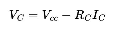
The voltage at the collector terminal is the supply voltage subtracted by the voltage drop across the collector resistance:
Meet the Author:

Hi, I’m Dominic. By day, I’m an engineer. By night, I repair and modify guitar effects! Since 2017, I’ve been independently modifying and repairing guitar effects and audio equipment under Mimmotronics Effects in Western New York. After coming out with a series of guitar effects development boards, I decided the next step is to support that community through content on what I’ve learned through the years. Writing about electronics gives me great joy, particularly because I love seeing what others do with the knowledge they gain about guitar effects and audio circuits. Feel free to reach out using the contact form!