
Guitar pedal battery switching, DC power disconnect, and expression pedal wiring explained
As a member of the Reverb Partner Program, eBay Partner Network, and as an Amazon Associate, StompboxElectronics earns from, and is supported by, qualifying purchases.
Disclaimer: Stompbox Electronics and/or the author of this article is/are not responsible for any mishaps that occur as a result of applying this content.
Introduction
Switches: the most engaging electromechanical component!
Available in all sorts of shapes, sizes, and configurations – switches give us the ability to interact with the electronic world. In this post, we’ll be covering a very particular type of switch technology that will help us design expression pedal controls and enable battery power switch-over.
Introducing: the switched jack – a component that performs switching functions through the physical act of plug insertion and removal. It appears in three distinct roles in guitar pedal design: battery power switching via the input jack, DC power switching at the barrel jack, and expression pedal control at the expression input jack.
Understanding how it works unlocks your ability to design battery-powered builds correctly, add power switching to existing circuits, and add expression pedal inputs to pedal designs that don’t have them.
Part 1: Connector Vocabulary
Before getting into switching behavior, here’s a brief vocabulary reference. Guitar pedal connectors use a standardized naming convention based on the number of conductors.
The TS (Mono) Plug and Jack
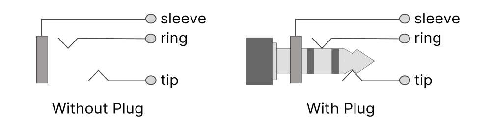
A Tip-Sleeve (TS) plug, also called a mono plug, has two electrical conductors. The tip connection carries the guitar signal while the sleeve serves as a reference, or ground, for the signal. A standard guitar cable uses a TS plug at both ends.
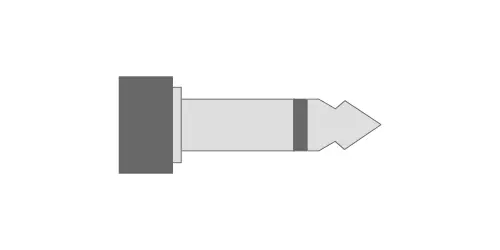
A mono jack has two contact points: one for the tip and one for the sleeve. When a TS plug is inserted, each segment of the plug makes contact with its corresponding jack contact.
The TRS (Stereo) Plug and Jack
A Tip-Ring-Sleeve (TRS) plug has three electrical conductors. The tip and ring each carry a separate signal – left and right audio in a stereo application – and the sleeve is ground. The ring is the short segment between the two insulating bands (shown in Figure 7.3).
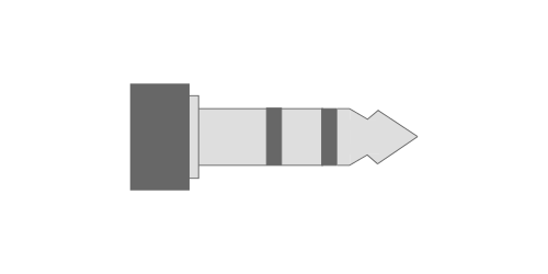
A stereo jack has three contact points: tip, ring, and sleeve. When a TRS plug is inserted, all three make contact with their respective connections.
The most common beginner mistake with jacks is ordering mono jacks for an application that requires stereo (or vice versa). Before ordering, count the contact lugs on the jack. A mono jack has two lugs. A stereo jack has three. If you are building a battery-powered pedal, you need a stereo jack at the input – even if your effect circuit is meant for a mono guitar signal. You’ll see why below!
Mounting Styles
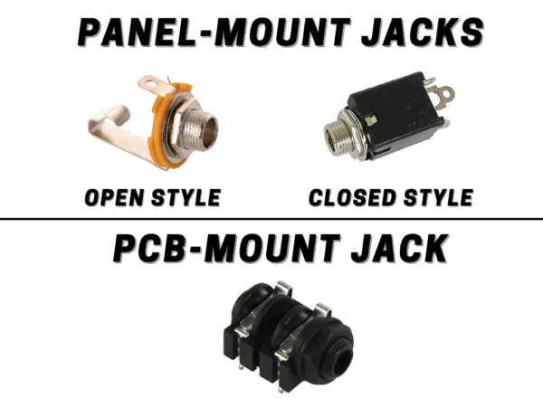
Both mono and stereo jacks are available in two mounting configurations:
A panel-mounted jack is a type of jack you can install in a hole in the enclosure and is usually fastened with a nut and washer. Panel-mounted jacks usually come with lugs for soldering a wired connection.
A board-mounted (or PCB-mounted) jack has pins that are inserted into copper-plated holes on a circuit board. The jack is then soldered directly into the board.
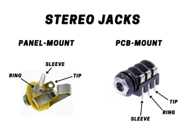
Similarly to mono jacks, stereo jacks come in different mounting configurations: panel-mount and PCB/board-mount.
Quick Reference: Jack Types in Guitar Pedals
| Type | Use | Conductors | Common Application |
|---|---|---|---|
| Tip-Sleeve (TS) | Mono | 2 | Standard guitar/signal cable |
| Tip-Ring-Sleeve (TRS) | Stereo / Expression | 3 | Expression pedal; stereo sends |
| Stereo jack w/ switch | Battery disconnect / Expression | 3 + switched | Input jack for battery pedals; expression inputs |
| Barrel jack (switched) | DC Power | 3 (switched) | DC power with auto battery disconnect |
Part 2: The Switching Mechanism
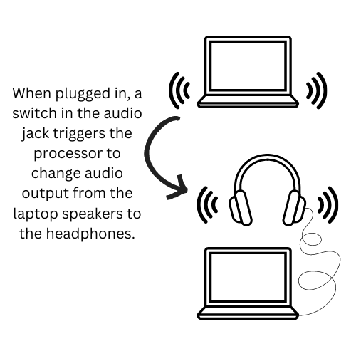
When you plug a pair of headphones into your laptop while playing music, what happens? The laptop transfers the audio signal from the speakers to the headphones automatically. This is all because of a tiny switch inside the headphone jack – a switched jack.
Other examples of switched jacks involve the use of expression pedals. Using the switches inside the jack, you can determine whether the Feedback control on a delay pedal should be controlled by a knob or by the expression pedal.
So how do these switches work exactly? Let’s take a look.
Stereo Switched Jack Operation
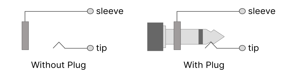
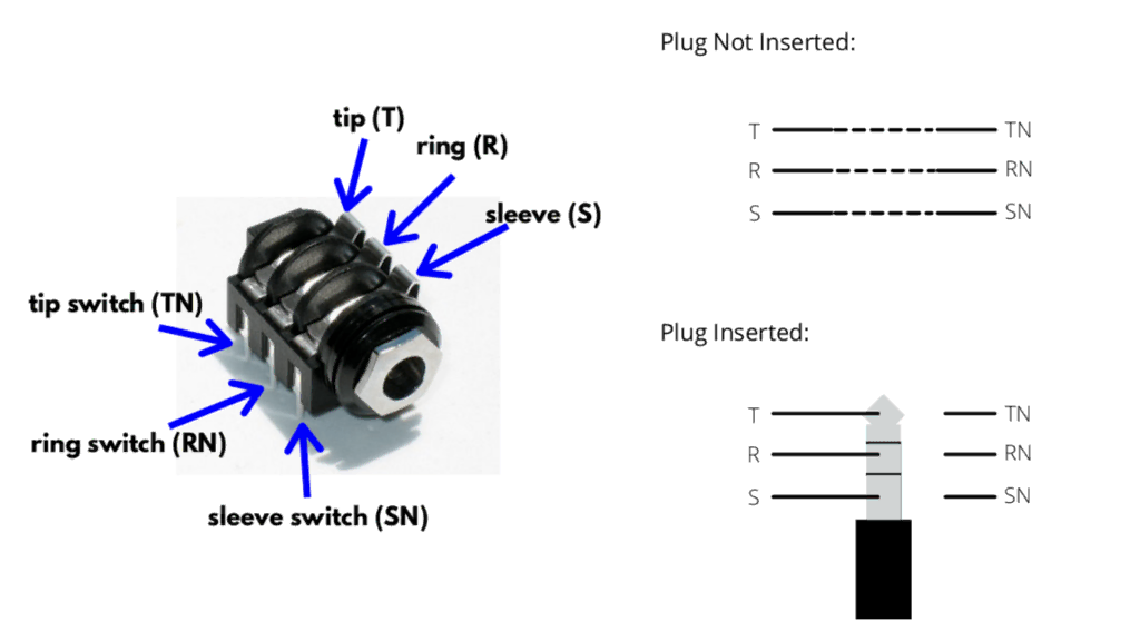
Switched jack operation is best explained using a diagram of the connectors. When looking at Figure 5.8, we see a stereo jack where the tip connection has an integrated switch, called the tip switch.
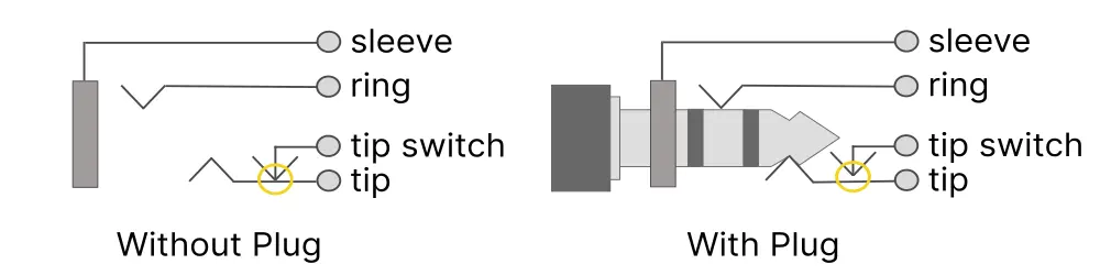
When the plug is not inserted into the jack, the tip switch is connected to the tip lug.
Inserting a plug pushes the tip connection out of the way so that the ‘tip switch’ disconnects from the tip, shown in the orange circle above.
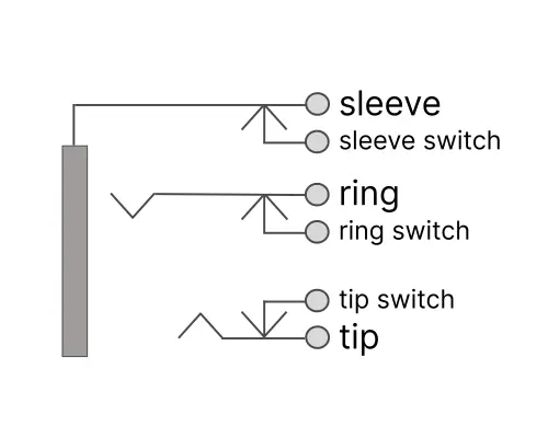
The same type of integrated switch can be installed for the ring and sleeve connections (Figure 5.9). Tip, ring and sleeve switches are commonly found on PCB-mount stereo connectors.
Part 3: Battery Switching via the Input Jack
The Problem: No Power Switch
From our first circuit, The Bypass, we learned that the typical footswitch is only wired to switch the input, output, and LED circuits. It does not cut power. If a pedal is powered by a battery, the circuit will be drawing current any time the battery’s negative terminal has a path to ground, regardless of whether the footswitch is in bypass or active mode. If you leave a pedal on a shelf for week, with a guitar cable plugged in, the battery will drain completely.
Early pedal designers solved this without adding a separate power switch: they routed the battery’s negative terminal through the ring lug of the switched input jack.
How It Works
The input jack on a battery-powered pedal is a stereo (TRS) jack wired in a specific way. The tip lug carries the audio signal, as expected. The sleeve lug connects to circuit ground, as expected. The ring lug is connected to the battery’s negative terminal – and that is the only path from the battery negative to ground.
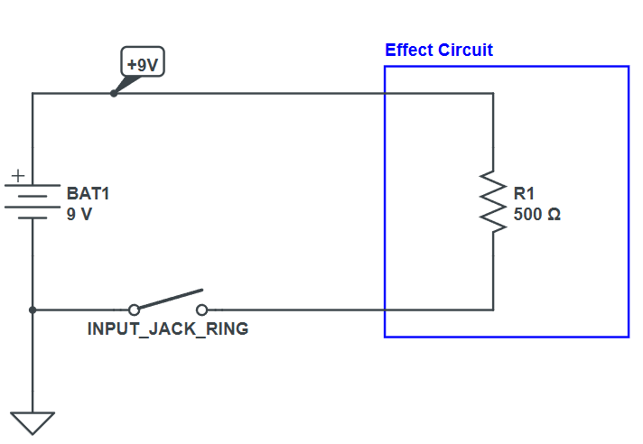
When nothing is plugged into the jack, the ring lug is isolated – it’s a dead end. The battery’s negative terminal has no path to ground, so no current can flow. The pedal is effectively off.
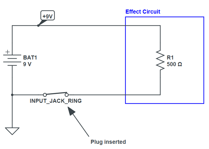
When a mono TS plug is inserted into a switched TRS input jack, the plug’s sleeve – a continuous metal tube – bridges the ring and sleeve contacts inside the jack. Now the negative terminal of the battery connects from the jack’s ring lug, through the plug sleeve, to the jack’s sleeve lug, which connects to circuit ground. Current flows. The pedal powers on.
This is why every battery-powered guitar pedal carries the instruction to unplug the instrument cable when not in use. The guitar cable IS the power switch. The ring lug of the input jack is the battery’s only path to ground. Leaving a cable plugged in – even if the pedal is in bypass – leave the circuit powered and the battery draining.
Why a Mono Cable Works on a Stereo Jack
A mono TS plug has only one insulating band, meaning its sleeve begins immediately after the tip segment (see Figure 5.1). When inserted into a stereo jack, the cable’s sleeve segment is long enough to simultaneously contact both the ring and sleeve contacts of the jack – physically shorting them together. This is the intentional behavior the circuit depends on.
A TRS stereo cable would not complete this switch. The ring segment of a TRS plug would sit isolated between the two insulating bands, and the sleeve of the TRS plug would contact only the sleeve lug of the jack – leaving the ring lug unconnected. This is why the battery switching only functions with a standard mono guitar cable.
Never use a TRS (stereo) cable as your guitar cable into a battery-powered pedal. The battery switching will not work, as there is no connection between the switch lugs to complete the battery circuit..
Part 4: The Switched DC Barrel Jack
The Second Switching Problem
The input jack handles battery on/off when you plug and unplug a guitar cable. But there is a second requirement: when a DC power supply is plugged in, the battery should disconnect automatically. Leaving both a DC power supply and a battery connected would drain the battery even when external power is available.
The switched DC barrel jack – the standard 2.1mm power connector found on virtually every guitar pedal – solves this with an internal spring-contact mechanism.
How the Switched Barrel Jack Works
Power plugs have two contacts: positive and negative. For BOSS pedals, the center pin is negative and the outer sleeve is positive (center-negative configuration).
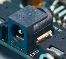
In practice, a switched power connector has 3 lugs. Two of the lugs take care of intercepting the positive and negative power rails. The third is a switched contact for the positive lug, which is used to power the pedal via battery when the adapter isn’t plugged in.
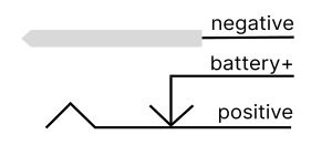
When a DC barrel jack is inserted, the barrel plug’s body physically pushes the battery+ pin away from the positive terminal, opening the spring contact. The battery’s positive terminal is now isolated, which disconnects it from the circuit. Instead, the DC supply’s outer sleeve connects to the positive terminal directly, powering the circuit.
The switched DC barrel jack only disconnects the BATTERY when DC is plugged in. The circuit still draws power. If you want the circuit to power off completely, you must still unplug either the DC supply of the guitar cable which disconnects the battery ground at the input jack.
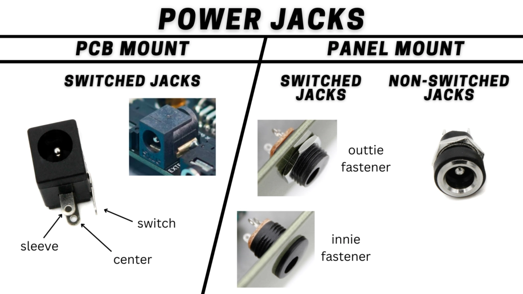
Types of Power Jacks
Putting It All Together: The Complete Power System
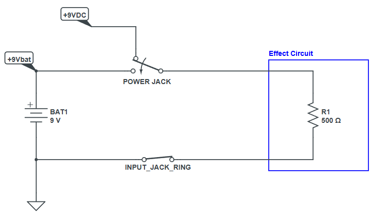
With both a stereo input jack (for battery-ground switching) and a switched DC barrel jack (for battery-positive switching), a fully battery-and-DC-capable pedal has four distinct power states, all managed entirely by mechanical jack contacts:
| Power State | What the jacks are doing | Result |
|---|---|---|
| Nothing Plugged In | Ring lug floating. No ground path. Battery dead-end | No power. Pedal off. |
| Guitar Cable Only (no DC) | Cable sleeve bridges Ring → Sleeve. Battery ground completes. | Battery powers circuit. |
| DC Supply + Guitar Cable | DC barrel plug separates battery + from positive. Battery → disconnected | DC supply powers circuit. Battery protected. |
| DC Supply Only (no guitar cable) | DC powers circuit. Input jack Ring still floating – but the battery already disconnected at barrel jack | DC powers circuit. Input ring state irrelevant. |
Part 5: Expression Pedal Inputs
How an Expression Pedal Works Electrically
An expression pedal is not a volume pedal. It does not sit inline with the audio signal. Instead, it sends a variable control signal to the host pedal, which uses that signal to modulate an internal parameter – delay time, filter frequency, effect mix, or anything else the designer chooses to expose.
Inside an expression pedal is a potentiometer. The rocking action of the pedal rotates the potentiometer, changing its resistance. The host pedal uses a TRS cable to both supply a reference voltage to the pot and read back the variable voltage from the pot’s wiper.
The ring pin of the TRS cable supplies a fixed reference voltage from the host pedal – typically derived from the supply rail. The tip pin is an input to the host pedal. The expression pedal’s pot wiper connects to the tip, and as the pedal rocks, the wiper moves between one end of the pot (near full reference voltage) and the other (near ground). The host pedal reads the tip voltage and uses it to set the parameter position.
Expression pedal polarity varies between manufacturers. The most common wiring (used by BOSS, Strymon, EHX, and many others) connects the pot CW leg to ring (reference) and wiper to tip. Some devices – notably Line 6 – use a difference TS configuration instead of TRS. Always check compatibility before connecting an expression pedal to an unfamiliar device.
The Switched TRS Jack: Defaulting to the Onboard Control
When no expression pedal is plugged in, the expression input’s tip and ring pins are floating. A floating input can cause the controlled parameter to drift, oscillate, or lock at an extreme value. The host pedal needs a way to route control back to the onboard potentiometer – whatever knob is on the pedal’s face – when no expression pedal is connected.
A switched TRS jack at the expression input solves this. This jack variant has additional spring contacts for the tip and ring connections. In the unplugged state, these springs connect the expression jack’s tip and ring pins to the onboard pot – exactly as if the onboard pot were wired directly to the parameter. The expression jack is transparent when empty.
When a TRS expression pedal plug is inserted, the plug body deflects both spring tabs, disconnecting the onboard pot and routing tip and ring to the expression pedal instead.
Mod Note: If you are adding an expression input to an existing pedal, you need a switched TRS jack – not a standard TRS jack. Without the switching contacts, the internal pot will be disconnected from the parameter when no expression pedal is plugged in, leaving the parameter floating with no control. This is one of the most common wiring mistakes when retrofitting expression inputs.
Expression Input Wiring in Practice
The standard approach when adding an expression input is to identify the three terminals of the pot you want to control – typically labeled CCW (counter-clockwise limit), wiper, and CW (clockwise limit). Run wires from those three terminals to the corresponding three lugs of the switched TRS jack, using the arm (switched) side of the jack’s spring contacts rather than the fixed contacts. The fixed contacts connect to the three pins of the TRS plug when an expression pedal is inserted. The spring contacts, when in the resting (unplugged) state, keep the internal pot in circuit.
Potentiometer value compatibility matters for expression inputs. Most expression pedals use 10kΩ to 100kΩ potentiometer. The host pedal’s circuit determines what values are compatible. Using a mismatched impedance won’t damage anything, but may result in a reduced sweep range or a non-linear response.
Summary: Three Applications, One Mechanism
The switched jack uses a spring-contact mechanism triggered by plug insertion and removal. That single mechanical behavior enables three distinct functions in guitar pedal designs:
- Battery power switching via the input jack – a stereo jack where the ring lug connects to the battery negative. Inserting a mono cable bridges ring to sleeve, completing the battery ground and powering the circuit. Removing the cable breaks the connection and disconnects the battery.
- DC/battery selection via the switched barrel jack – a three-lug DC connector where a normally-closed spring contact connects battery positive to the circuit. Inserting a DC plug opens the spring and disconnects the battery, allowing a DC supply to power the circuit instead.
- Expression input switching via the switched TRS jack – an expression input jack with additional spring contacts that keep the onboard pot in circuit when no expression pedal is plugged in, and automatically hand control to the expression pedal when one is inserted.
All three use the same physical principle, applied differently. Once you understand the spring-contact mechanism, you can design and troubleshoot all of these configurations from first principles.
References
[1] Beavis Audio – Stompbox Power Anatomy
[2] Amplified Parts – Jack and Footswitch Wiring
[3] Mission Engineering – Understanding Expression Pedals
[4] How Expression Pedals Work (expressionpedals.com)
Guitar Effects Design in 48 Circuits or Less
This post is part of the 48 Circuits or Less series by Stompbox Electronics. Each installment covers one fundamental pedal circuit building block – concept, demonstration, and supplemental resources.
View more articles in this series here.

Meet the Author:

Hi, I’m Dominic. By day, I’m an engineer. By night, I repair and modify guitar effects! Since 2017, I’ve been independently modifying and repairing guitar effects and audio equipment under Mimmotronics Effects in Western New York. After coming out with a series of guitar effects development boards, I decided the next step is to support that community through content on what I’ve learned through the years. Writing about electronics gives me great joy, particularly because I love seeing what others do with the knowledge they gain about guitar effects and audio circuits. Feel free to reach out using the contact form!
The Tools I Use
As a member of Amazon Associates, Stompbox Electronics earns and is supported by qualifying purchases.


