

By: Dominic Sciarrino | Stompbox Electronics | Last Updated: February 26th, 2026
As a member of the Reverb Partner Program, eBay Partner Network, and as an Amazon Associate, StompboxElectronics earns from, and is supported by, qualifying purchases.
Disclaimer: Stompbox Electronics and/or the author of this article is/are not responsible for any mishaps that occur as a result of applying this content.
Introduction
You’ve plugged a 9V power supply into a guitar pedal. But the circuit inside isn’t running 9 volts everywhere. Different stages need different voltages to operate correctly. A transistor amplifier stage needs a specific bias point. An op-amp needs a reference to work from. Where do those voltages come from?
The answer, in most single-supply guitar pedal circuits, is the voltage divider. It is two resistors and nothing else, yet it appears in virtually every analog pedal ever designed. Understanding it is non-negotiable if you want to understand how pedal circuits work.
This post also introduces the potentiometer as a variable voltage divider, which is the foundation of every volume control and most tone controls you’ll ever wire up.
Part 1: Why Does a Pedal Need a Bias Voltage?
Your Guitar Signal is Centered at Zero
Your guitar produces a continuously varying voltage that swings above and below zero volts. The positive peaks go above ground; the negative troughs dip below it. On an oscilloscope, it looks like a wave oscillating around the 0V line. In other words, your guitar signal is an AC signal.
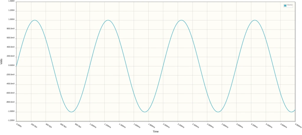
This is perfectly normal. It’s how AC signals work. But it creates a problem when you try to process that signal inside a guitar pedal.
The Single-Supply Problem
A typical guitar pedal runs on a single 9V supply. That supply provides voltages between 0V (ground) and +9V. It produces no negative voltages on its own*.
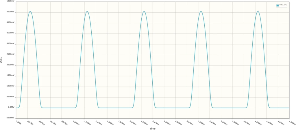
When you feed a guitar signal into a circuit powered this way, the negative half of the signal falls outside the range the circuit can handle. The transistors or op-amps in the circuit simply cannot process a voltage below their ground reference. That portion of the signal gets clipped off.
*There is an alternative: use a dual-supply power source that provides both positive and negative voltages (for example +9V and -9V). Some pedal circuits do this using a charge pump inverter. That’s covered in Circuit 10 – The Charge Pump Inverter. For now, we focus on the more common single-supply approach.
Biasing: Shifting the Signal Into Range
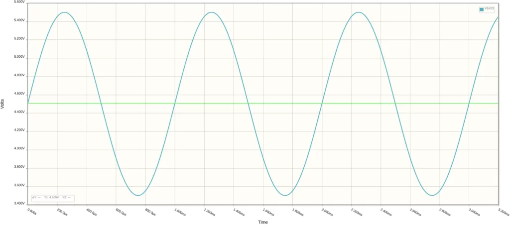
The solution is to shift the entire waveform upward so that both the positive and negative swings stay within the circuit’s operating range. This process is called biasing.
Biasing superimposes the AC guitar signal on top of a fixed DC voltage. The AC component still swings the same amount above and below its center, except now that center is above zero, and the whole waveform lives in positive territory.
The standard approach for single-supply pedal circuits is to bias at half the supply voltage. On a 9V supply, that means generating a 4.5V DC reference. The signal swings equally above and below 4.5V, keeping the peaks below 9V and the troughs above 0V.
The 4.5V bias point is one of the most frequently referenced values in single-supply guitar pedal circuit design. Any time you see ‘Vref’, ‘Vbias’, or a resistor divider with its output labeled ‘bias’ on a schematic, this is what it is generating.
Part 2: The Voltage Divider Circuit
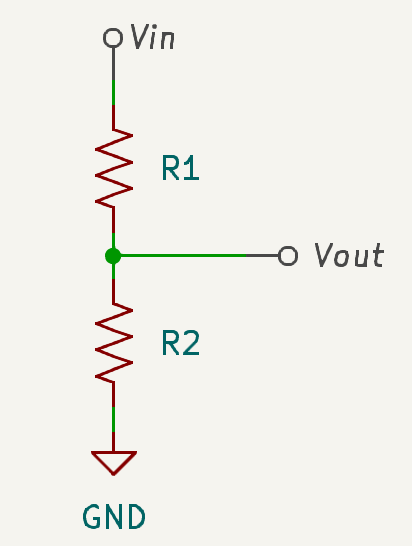
The circuit that generates the bias voltage is called a voltage divider. It consists of two resistors in series, connected between the supply voltage and ground. The output (the bias voltage) is taken from the junction between the two resistors.
The Voltage Divider Equation
The output voltage is determined by the ratio of R2 to the total resistance. The equation is:

In plain language: Vout is a fraction of Vin. That fraction equals R2 divided by the sum of both resistors. If R1 and R2 are equal, R2 is exactly half the total, so Vout is exactly half of Vin.
Example 1: Equal Resistors
R1 = 10kΩ
R2 = 10kΩ
Vin = 9V
Vout = 9 x (10k / 20k)
Vout = 9 x 0.5
Vout = 4.5V ✓
Equal values → half the supply voltage
Example 2: Unequal Resistors
R1 = 20kΩ
R2 = 10kΩ
Vin = 9V
Vout = 9 x (10k / 30k)
Vout = 9 x 0.333
Vout = 3V ✓
R2 is 1/3 of total → 1/3 of supply
You don’t need to do the math by hand. The Stompbox Electronics voltage divider calculator will solve for any target voltage, given your supply voltage and resistor values.
Choosing Resistor Values
The Ratio Determines the Voltage
The resistor ratio is what sets Vout. Equal resistors give half the supply. A 2:1 ratio (R1:R2) gives one-third the supply. You can achieve any target voltage by choosing the right ratio.
For the standard 4.5V bias point on a 9V supply, any two equal-value resistors will work. Common choices are 10kΩ, 22kΩ, 47kΩ, or 100kΩ.
The Values Determine Reliability and Loading
Here is something the equation alone doesn’t tell you. The actual resistor values determine how well the divider holds its output voltage when another circuit is connected to it.
When you connect the bias output to an effect circuit, that circuit has its own input impedance. To the voltage divider, the effect circuit “looks like” a resistor in parallel with R2. That parallel combination reduces the effective value of R2, which shifts Vout lower than you calculated.
This is called loading. The connected circuit is loading the voltage divider.
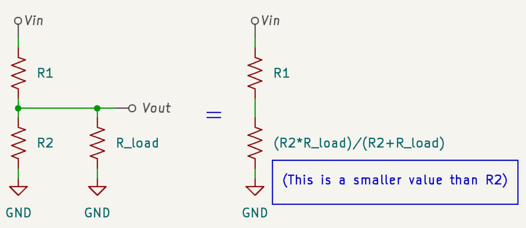
The way to minimize loading is to use smaller resistor values in the divider. A lower-value divider naturally draws more current from the supply and is less affected by the relatively higher impedance of the load. The load becomes a smaller fraction of the parallel combination.
But smaller resistors waste more current and can generate heat. There is a tradeoff.
Rule of thumb: voltage divider resistors should be at least 10x smaller in value than the input impedance of the circuit they are biasing. In guitar pedal circuits, values between 10kΩ and 100kΩ work well for most single-supply bias applications.
Part 3: The Variable Voltage Divider (Volume Control)
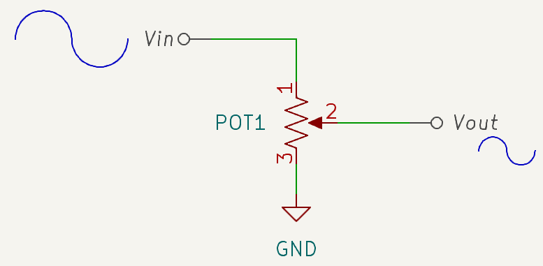
The voltage divider doesn’t have to use two fixed resistors. If you replace the entire divider with a potentiometer then you have a variable voltage divider. Potentiometers (or “pots“) are essentially a resistor with a moveable wiper that allows you to tap off a variable resistance.
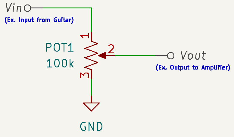
This is exactly how passive volume control works in guitars and guitar pedals.
The input signal enters at the top of the potentiometer. Ground is at the bottom. The wiper output goes to the next stage of the circuit. As you turn the pot clockwise:
- Wiper at bottom: full resistance above, zero below → The output is connected directly to ground, signal is silenced.
- Wiper at center: half the pot resistance above and below → The signal is attenuated to roughly half its normal amplitude.
- Wiper at top: full resistance below, zero above → full signal passes to the output through the wiper.
This same principal – a signal input at the top of a pot, ground at the bottom, output from the wiper – is the basis of almost every volume, gain, and level control you will encounter in guitar pedal design.
Linear taper potentiometers divide the resistance evenly across rotation. Audio taper (logarithmic) potentiometers are weighted to match the logarithmic response of human hearing. Turning the knob from 0 to 5 changes perceived volume by the same amount as turning from 5 to 10. For volume controls, audio taper usually feels more natural. For bias or gain controls, linear taper is typically used.
Part 4: Exercises
Exercise 1: Verify the Equation
Build a voltage divider on the breadboard using two 10kΩ resistors. Connect the input to your 9V supply rail and ground at the bottom. Measure the output voltage with a multimeter. It should read approximately 4.5V.
Then, swap R1 for a 47kΩ resistor (keeping R2 at 10kΩ). Predict the new Vout using the equation before you measure. Then measure and compare.
Exercise 2: Observe Loading
With the 10kΩ / 47kΩ divider built, place a 10kΩ resistor in parallel with R2 (from the Vout node to ground). This simulates a circuit with a 10kΩ input impedance connected to your bias point. Measure Vout again.
- Compare to the unloaded value.
- Compare to the theoretical prediction using the equation with the parallel combination as the effective R2.
Exercise 3: Build a Volume Control
Wire a 100kΩ potentiometer as a voltage divider with your guitar signal at the top terminal and ground at the bottom terminal. Take the output from the wiper. Connect the wiper to an amplifier. Sweep the pot and observe the signal level changing.
Parts List
| Part | Quantity |
|---|---|
| 10kΩ Resistor | 2 |
| 47kΩ Resistor | 2 |
| 100kΩ Potentiometer (linear taper) | 1 |
| Breadboard (or PROTIS 1 board) | 1 |
| Multimeter | 1 |


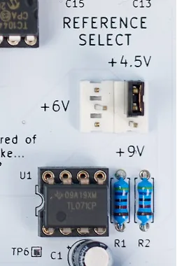
The Reference Voltage Generator on the PROTIS 1
The PROTIS 1 Development Board includes a built-in reference voltage generator circuit – a voltage divider with selectable output. The reference select header on the right side of the board offers three options via a jumper:
- 4.5V – use when the circuit is powered by 9V (standard)
- 6V – use when the circuit is powered by 12V
- 9V – use when the circuit is powered by 18V
Access the reference output via the REFERENCE header along the right side of the prototyping area using a male-to-male jumper wire. Connect this to any node in your breadboarded circuit that requires a bias voltage.
References
[1] Stompbox Electronics Voltage Divider Calculator
[2] R.G. Keen – Bias Network Resistor Selection (Geofex)
[3] Iota Pedals – Voltage Divider Basics
Guitar Effects Design in 48 Circuits or Less
This post is part of the 48 Circuits or Less series by Stompbox Electronics. Each installment covers one fundamental pedal circuit building block – concept, demonstration, and supplemental resources.
View more articles in this series here.
Meet the Author:

Hi, I’m Dominic. By day, I’m an engineer. By night, I repair and modify guitar effects! Since 2017, I’ve been independently modifying and repairing guitar effects and audio equipment under Mimmotronics Effects in Western New York. After coming out with a series of guitar effects development boards, I decided the next step is to support that community through content on what I’ve learned through the years. Writing about electronics gives me great joy, particularly because I love seeing what others do with the knowledge they gain about guitar effects and audio circuits. Feel free to reach out using the contact form!
The Tools I Use
As a member of Amazon Associates, Stompbox Electronics earns and is supported by qualifying purchases.


