
By: Dominic Sciarrino | Stompbox Electronics | Last Updated: February 23, 2026
As a member of the Reverb Partner Program, eBay Partner Network, and as an Amazon Associate, StompboxElectronics earns from, and is supported by, qualifying purchases.
Disclaimer: Stompbox Electronics and/or the author of this article is/are not responsible for any mishaps that occur as a result of applying this content.
Introduction
Every guitar effects pedal has to solve one problem before it does anything else: how to switch the signal on and off. That’s the bypass circuit.
Most explanations treat bypass as a single thing, but that framing misses something important. There are actually two separate decisions happening in every bypass circuit:
- The Signal Path – What happens to your guitar signal when the pedal is off?
- The Switching Method – What physically controls that transition?
These two things are independent of each other. You can mix and match them in any combination that makes sense for your design. Understanding both, and how they interact, is the foundation for understanding every bypass circuit you’ll ever encounter.
This post covers three signal path types and both switching methods, with wiring diagrams for the most common combinations.
Part 1: The Signal Path
The signal path describes what happens to your guitar signal when the pedal is in bypass mode. There are three types.
Simple Bypass
In simple bypass, the effect circuit input is permanently connected to your guitar signal – whether the pedal is on or off. The switch doesn’t disconnect the circuit. Instead, it selects which output you hear: the processed signal from the effect, or the dry signal routed around it.
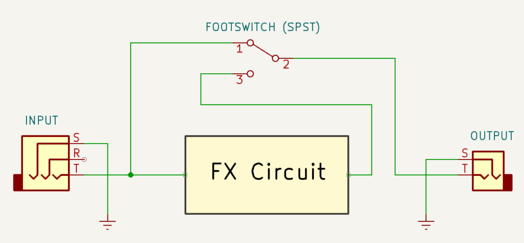
Even in bypass mode, your signal is exposed to the input stage of the effect circuit. If that stage loads your signal, adds noise, or has any impedance character, you hear it whether the pedal is on or off.
This is why certain vintage pedals affect your tone even when bypassed. It’s not a defect, it’s a consequence of the bypass topology. Many players use this intentionally, placing a pedal with a desirable input stage early in their chain for its bypass coloration.
Simple bypass is most common in vintage designs. It requires only a Double-Pole Double-Throw (DPDT) or Single-Pole Double-Throw (SPDT) switch and is the simplest possible implementation.
True Bypass
True bypass completely disconnects the effect circuit from the signal path when the pedal is off. The input jack connects directly to the output jack through the switch. This means your input signal is not exposed to the input stage of the pedal’s circuit at all, so there are no loading or coloration effects. In other words, your signal is electrically isolated from the effect circuit.
Figure 1.2 below presents a clear idea of what we’re aiming for. The switch SW1 is called a double-pole double-throw switch (DPDT). The number of poles signify the number of ‘switches’. The number of throws signifies how many directions you’re able to set for each pole.
In this case, there are 2 poles: SW1a and SW1b. Each pole has two possible directions (“double”-throw). The first pole (SW1a) is used to route the input signal. The other pole (SW1b) is used to route the output signal.
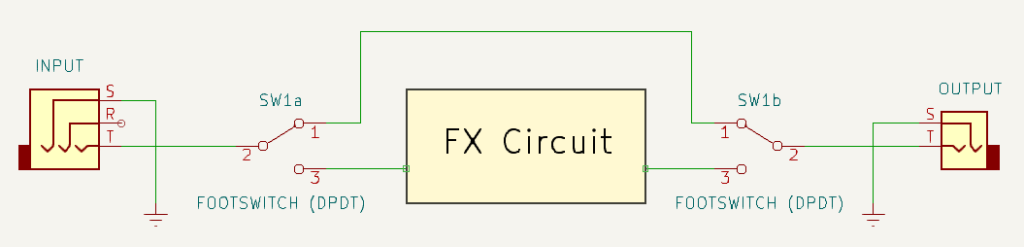
When the pedal is engaged, the switch routes the signal into the effect circuit, and the processed output connects to the output jack.
True Bypass is the dominant approach in boutique and DIY pedal design. It is the most transparent bypass topology available – when the pedal is off, it genuinely has no effect on your signal.
There is one limitation: cable capacitance. Long cables roll off high frequencies. If you put many true bypass pedals in a chain, it electrically looks like a long cable run. To solve the roll off issue you can’t rely on True Bypass. Instead, you will need a buffered bypass somewhere in your chain.
True bypass is implemented with a Triple-Pole Double-Throw (3PDT) footswitch in most boutique and DIY designs. The 3PDT gives you three independent switching contacts for signal, return, and an LED indicator – all controlled by a single stomp of the switch.
Testing a Guitar Pedal for True Bypass
A True Bypass pedal in bypass mode will allow your guitar signal to pass through it whether or not power is applied to the pedal.
It’s easy to test if your pedal is True Bypass, just follow these steps:
- Plug a guitar into the pedal’s input.
- Plug an amp into the pedal’s output.
- Ensure there is no power applied to the guitar pedal.
- While the pedal is in bypass mode, turn on the amp and try to play through the pedal.
If you hear your guitar signal while the pedal is in bypass mode, then you have a True Bypass pedal!
The method above does not differentiate between Simple Bypass and True Bypass. However, if the pedal would be considered “modern” (i.e. not vintage) then it’s safe to rule out Simple Bypass.
Buffered Bypass
Buffered bypass is a variation on true bypass. The effect circuit is still disconnected from the signal path in bypass mode – so the circuit itself has no electrical contact with your signal.
The difference is that the dry signal passes through a buffer stage on its way to the output, even when the pedal is bypassed.
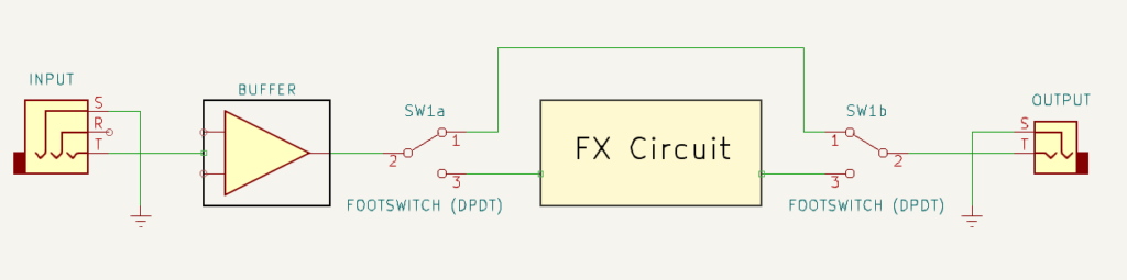
A buffer presents a high input impedance and a low output impedance. This counteracts cable capacitance and preserves high-frequency content across long cable runs. The buffer drives the cable, so the cable no longer loads the signal source.
The tradeoff is that your signal is always passing through an active circuit. A well-designed buffer is inaudible. A poorly designed buffer can add noise, alter frequency response (i.e. tone), or interact unexpectedly with certain pickups. This is why buffer quality matters, and why dedicated buffer pedals exist as a product category.
Buffered bypass is the right solution for large pedalboard rigs with long cable runs. A quality buffer placed early in your chain is often the single most impactful change you can make to your overall signal integrity.
Part 2: The Switching Method
The switching method describes what physically controls the bypass transition. There are two categories: (1) mechanical and (2) electronic.
Mechanical Switching
Mechanical switching uses a physical switch (typically a DPDT or 3PDT) that the player stomps directly. The switch contacts are what route the signal.
The 3PDT Switch
The 3PDT (three-pole double-throw) is the standard for true bypass in boutique and DIY design. It provides three independent switching contact groups that all change state simultaneously with one press.
Each pole handles one job:
- Pole 1: Signal switching – routes the input either to the effect circuit or directly to the output.
- Pole 2: Return switching – routes the output jack either from the effect circuit or from the direct bypass path.
- Pole 3: LED indicator – connects the LED to power on when the effect is engaged
The wiring diagram in Figure 1.4 is one of the most common ways to wire a True Bypass switch. You can use this picture as a guide.
Referencing the block diagram in Figure 1.2, the first column of lugs represents SW1a while the second column represents SW1b. The third column is the additional pole used to switch ON and OFF an LED.
Here is a quick video describing the same 3PDT configuration:
The DPDT Switch
The DPDT (double-pole double-throw) provides two switching contact groups. It’s used where a third pole isn’t needed. For example, in simple bypass designs, or where LED switching is handled by a separate circuit.
Mechanical switches are reliable, inexpensive, and require no power to function. Quality 3PDT switches are typically rated for 30,000 to 100,000 actuations.
Electronic Switching
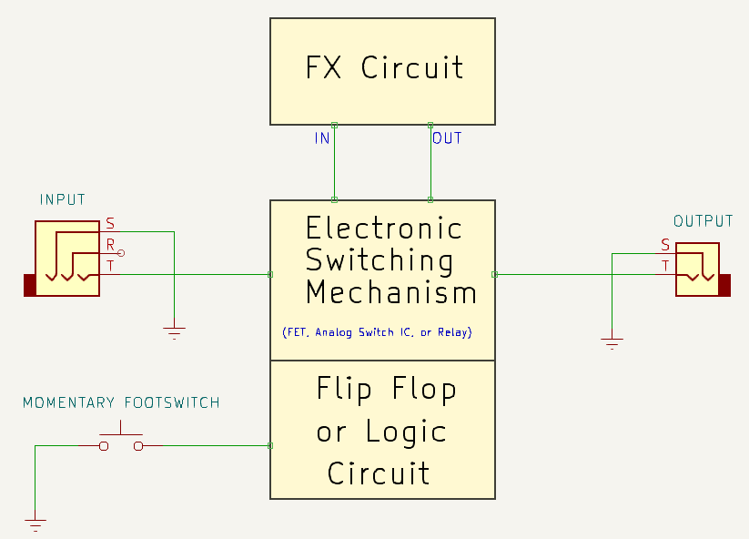
Electronic switching replaces mechanical switch contacts with an electronic component controlled by a logic circuit. Common electronic components used for electronic switching are FET transistors, analog switch ICs, or a relay.
The footswitch in an electronically switched pedal serves as a momentary trigger only. It carries no signal. A logic circuit – typically a transistor flip-flop or CD4013 CMOS flip-flop IC – remembers the states and drives the actual switching element.
FET Switching
A field-effect transistor (FET) opens or closes a signal path based on the voltage applied to its gate. When the flip-flop drives the gate high, the drain-source channel conducts and the signal passes. When the gate is pulled low, the channel opens and the signal is interrupted.
FET switching is used by BOSS, Ibanez, MXR, and Danelectro. It is fast, completely silent, and has no mechanical wear. The FET does have a small on-resistance when conducting, but is generally negligible.
Analog Switch IC
Dedicated analog switch integrated circuits (ICs) such as the CD4066 contain multiple FET-based switching elements in a single package. They are commonly used in more complex routing applications or when multiple signal paths need to be switched simultaneously.
Relay Switching
A relay is an electromechanical device driven by the logic circuit. The relay’s physical contacts – not a semiconductor – switch the signal. This gives relay bypass the signal integrity characteristics of true bypass (metal contacts, no semiconductors in the path) with the control characteristics of electronic switching (silent, remotely triggerable, no direct mechanical connection to the footswitch).
Relay bypass is used in higher-end designs where both signal transparency and silent electronically controlled switching are required.
The Full Picture: Bypass Type vs. Switching Method
Signal path type and switching method are independent design decisions. The table below shows all six combinations with real-world examples.
| Simple Bypass | True Bypass | Buffered Bypass | |
|---|---|---|---|
| Mechanical | Vintage pedals with DPDT. Signal always exposed to circuit. | Most boutique pedals and DIY builds. 3PDT footswitch. | Less common. Mechanical switch routes dry signal through buffer. |
| Electronic | Rare in modern designs. | Higher-end or small form factor (mini) relay-bypass. True bypass quality, silent switching. | Found in various BOSS, Ibanez, MXR, Danelectro pedals. FET flip-flop + always-on buffer. |
The two most common combinations in practice are True Bypass + Mechanical and Buffered Bypass + Electronic. The others exist and are valid, some more than others.
Where to Buy
Guitar pedal footswitches are easily found doing a quick internet search. There are large electronics distributors like Mouser, DigiKey, Arrow, and Newark that are readily accessible for basic electronic components.
For guitar pedal parts specifically, you’ll need to look at more niche distributors. LoveMySwitches, Small Bear Electronics, GuitarPedalParts, and DIYPedalGearParts are all good options.


True Bypass with the PROTIS 1
The PROTIS 1 Development Board has a True Bypass circuit embedded into it’s design. For this reason, when you design your effects on the PROTIS 1, there is no need to build the True Bypass circuit yourself when prototyping.
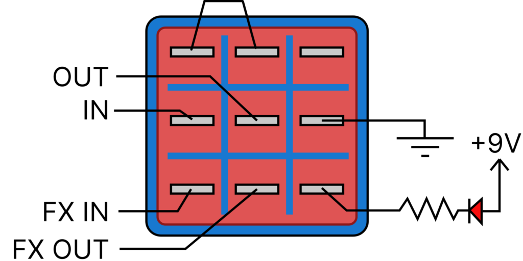
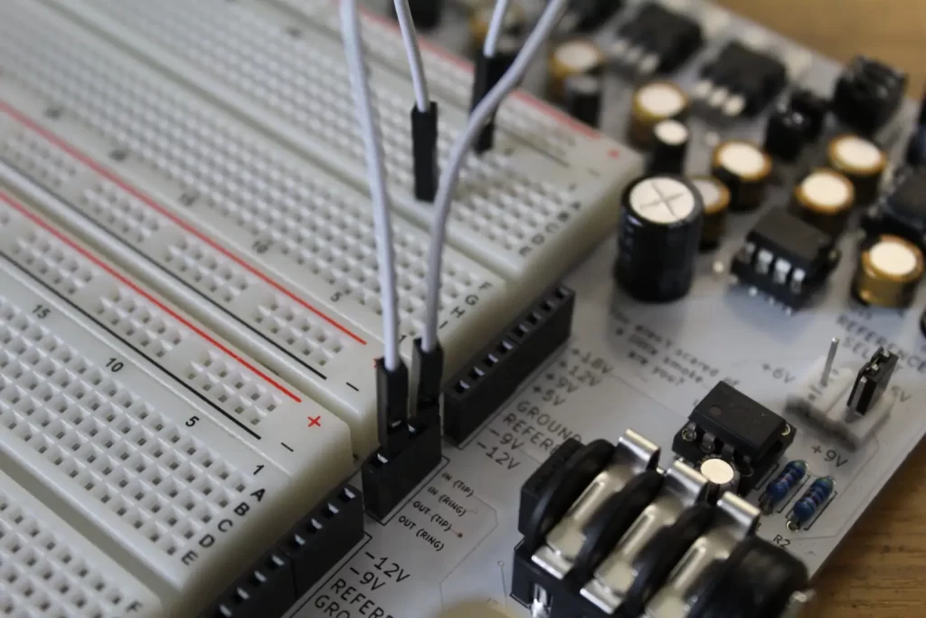
If you’re following along using the PROTIS 1, take a look at the input/output headers.
The input signal comes from a terminal marked IN (TIP). Likewise, the output signal goes to the OUT (TIP) terminal.
Plug your guitar into the input jack, located on the right side of the board. Plug your amp into the output jack, located on the left side of the board.
When you strum, you should hear your guitar signal playing through the amp. If you can’t hear it, then the board is not in “bypass” mode. Press on the 3PDT switch to toggle between Engaged Mode to Bypass Mode.
Example Bypass Circuits
By now you should know that the wiring scheme in Figure 1.4 isn’t the only way to bypass a guitar pedal. Other methods have been developed over the years, including the Millennium Bypass, CD4053 Bypass, and Relay Bypass.
Millennium Bypass
The 3PDT switch allows you to have True Bypass and an indicator light. However, 3PDT switches are more expensive than their DPDT counterparts, so it would be great to have a bypass circuit that gives us the benefits of True Bypass and an indicator LED using the less expensive DPDT switch.
In 1999 R.G. Keen noticed the DPDT switching method used in later RAT pedals could be improved. He figured out a way to add in an indicator LED while reducing the load on the output signal, all using the cheaper DPDT and a handful of parts. He called this method the Mellenium Bypass.
Relay True Bypass
Another way to construct a True Bypass circuit is by using a relay. A relay is a device that uses magnetism to perform switching.
It works like this: a coil of wire becomes energized by applying a voltage across it. The current flowing through that coil produces a magnetic field which closes a pair of metal contacts. If you remove the voltage, it halts the current flow through the coil and kills the magnetic field, which allows the contacts to open.
This method is more advanced, since it usually requires a microcontroller and a specially designed circuit for energizing and de-energizing the relay coil. Most microcontrollers cannot handle the standard 9Vdc voltage used in modern pedal designs. For this reason, a 5Vdc regulator is also often required to power the microcontroller circuit. Many modern pedals utilize this method, like the Line 6 DL-4 among others.
For DIY, if you do not have microcontroller experience you can still opt to purchase ready-to-use kits, complete with parts, a programmed chip, and a circuit board.
Additionally, if you’re a proud owner of a PROTIS 1 development board and interested in working with microcontroller circuits, check out the PROTIS 1 PIC Development Board Module.
CD4053 Bypass
In another 2000 GeoFex article, R.G. Keen described another electronic bypass method using two integrated circuits (ICs): the CD4053 and CD4013. This method is utilized in most Behringer pedals and is not considered True Bypass, because the ICs require power to carry the signal.
The CD4053 3PDT Analog Switch is basically an electronic equivalent to the mechanical 3PDT switch described above. The CD4053 chip requires an ON/OFF electrical signal to bypass/engage the switching mechanism.
The CD4013 Dual D Flip-Flop IC is often used to provide the “toggle” signal to the CD4053. To trigger the toggle action, you can use a simple momentary switch connected to the CD4013.
BOSS-Style JFET Bypass
BOSS and Ibanez pedals employ JFETs (Junction Field-Effect Transistors) to handle bypassing. This is not a True Bypass method, but it is popular and worth reading up on if you are interested in modifying BOSS pedals. Read more about the BOSS/Ibanez style bypass switching here.
Guitar Effects Design in 48 Circuits or Less
This post is part of the 48 Circuits or Less series by Stompbox Electronics. Each installment covers one fundamental pedal circuit building block – concept, demonstration, and supplemental resources.
View more articles in this series here.


Meet the Author:

Hi, I’m Dominic. By day, I’m an engineer. By night, I repair and modify guitar effects! Since 2017, I’ve been independently modifying and repairing guitar effects and audio equipment under Mimmotronics Effects in Western New York. After coming out with a series of guitar effects development boards, I decided the next step is to support that community through content on what I’ve learned through the years. Writing about electronics gives me great joy, particularly because I love seeing what others do with the knowledge they gain about guitar effects and audio circuits. Feel free to reach out using the contact form!
The Tools I Use
As a member of Amazon Associates, Stompbox Electronics earns and is supported by qualifying purchases.


