
By: Dominic Sciarrino | Stompbox Electronics | Last Updated: April 9th, 2026
Most guitar effects circuits run directly from a 9V supply with no voltage regulation required. The moment a digital component enters the design (i.e. a PT2399 echo processor, a microcontroller, a DSP chip) that changes. Digital ICs commonly require 5V or 3.3V, and the linear voltage regulator is the standard, practical way to produce those voltages from a 9V supply. This article covers what a linear regulator does, when a builder needs one, the three parameters that determine whether a regulator will work in a given design, how to calculate heat dissipation, and how to implement both fixed and adjustable regulators.
As a member of the Reverb Partner Program, eBay Partner Network, and as an Amazon Associate, StompboxElectronics earns from, and is supported by, qualifying purchases.
Disclaimer: Stompbox Electronics and/or the author of this article is/are not responsible for any mishaps that occur as a result of applying this content.
What a Linear Voltage Regulator Does
A linear voltage regulator accepts an input voltage that is higher than required and outputs a lower, stable, regulated voltage regardless of variations in the input voltage or load current. That stability is its primary value. If the supply voltage from the wall-wart fluctuates, the regulated output holds steady. If the downstream circuit draws more current, the output holds steady.
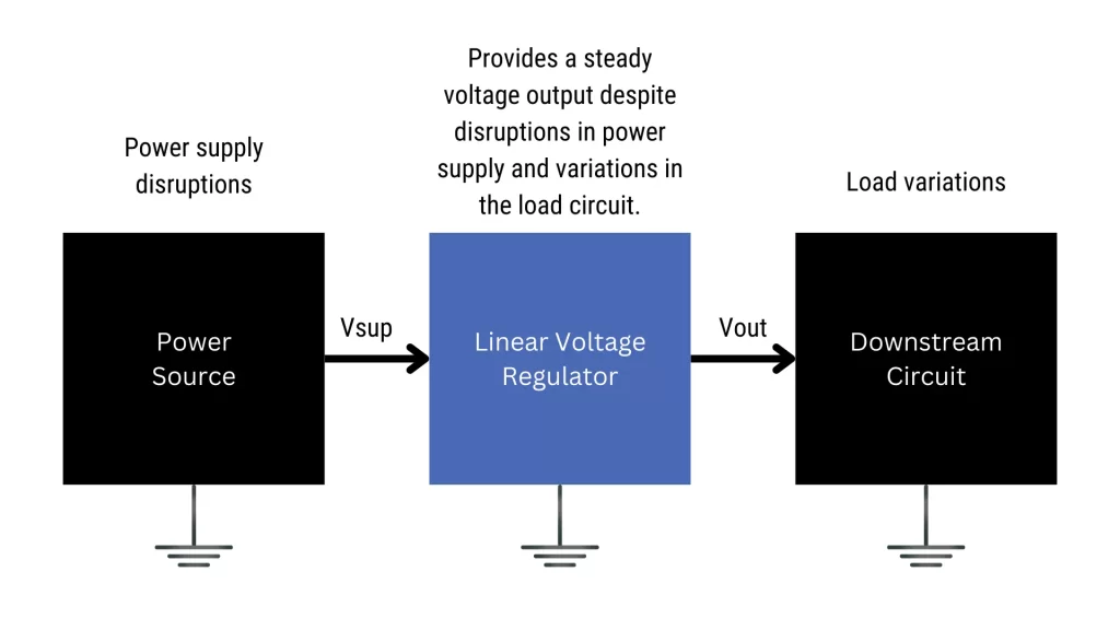
Internally, a linear regulator contains a pass element (typically a transistor) wired between the input and output. A feedback circuit continuously monitors the output voltage and adjusts the pass element’s resistance to maintain the correct output level. If the output rises, resistance increases to pull it back. If the output drops, resistance decreases to let more current through.
Because the excess voltage (input voltage – output voltage) is lost as heat rather than recovered, managing the thermal load is critical. This reality directly dictates your choice of components and cooling strategies (see the Heat Dissipation section below).
When a Build Needs a Linear Regulator
Linear regulators are not needed in most all-analog guitar effects designs. A standard overdrive, boost, fuzz, or compressor circuit runs directly from the 9V supply rail with no regulation required. The linear regulator becomes necessary when the design includes a component that requires a supply voltage different from what the main supply provides.
The two scenarios a builder will encounter most often:
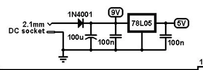
- PT2399 echo/delay circuits: The PT2399 is one of the most widely used ICs in DIY delay and echo pedal designs. It requires a 5V supply. Since most pedal designs are powered at 9V, a 5V linear regulator is a standard inclusion in any PT2399-based design. The Valve Wizard Small Time design is a well-known example, using a 78L05 (a low-power 5V regulator) to supply the PT2399 cleanly from the 9V rail.
- Microcontroller-based designs: Older microcontrollers such as the ATmega328 (Arduino UNO) require 5V. Newer ARM-based microcontrollers (ESP32, STM32 series, and Raspberry Pi RP2040) require 3.3V. Any pedal design incorporating a microcontroller needs the appropriate regulated rail.
Quick rule: All-analog design? A linear regulator is probably not needed. Digital IC in the design? Check its supply voltage requirement in the datasheet. If it differs from your main supply voltage, you need a linear regulator.
The Three Parameters That Matter
Before selecting a regulator, three parameters need to be understood and verified against the design requirements.
1. Output Voltage
The output voltage is the regulated voltage the device maintains at its output terminal. Fixed regulators have a manufacturer-preset output voltage that cannot be changed. For example, the 7805 always outputs 5V, and the 7812 always outputs 12V. Adjustable regulators like the LM317 allow the output voltage to be set with external resistors, covering a continuous range from 1.25V to 37V.
2. Dropout Voltage
Dropout voltage is the minimum difference required between input and output voltage for the regulator to maintain regulation. If the input voltage drops too close to the output voltage, the regulator loses control of the output.
For a standard 7805, the dropout voltage is typically 2 to 3 volts. This means the input must be at least 7 to 8V for reliable 5V output. From a 9V supply that’s comfortable margin, but if the supply sags under load or a battery is running down, the margin erodes.
Low-Dropout (LDO) regulators are designed to minimize the dropout voltage at typically 0.3V or less. This becomes particularly important in battery-powered designs, where supply voltage gradually falls as the battery discharges. An LDO can maintain regulation much closer to the battery’s depleted voltage than a standard regulator. For 3.3V designs powered from a 9V supply, the dropout voltage of a standard regulator is not an issue, but for designs where the supply margin is tight, always verify the dropout specification.
3. Maximum Output Current
Every regulator has a maximum output current rating. Exceeding it causes the output voltage to drop and the device to overheat. Common current ratings in DIY pedal design:
| Package | Typ. Current Rating | Common Use |
|---|---|---|
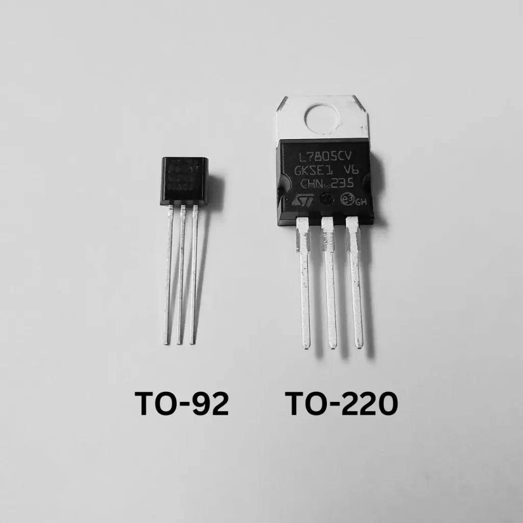
| TO-92 (78Lxx series) | 100 mA | PT2399, low-current digital ICs |
| TO-220 (78xx series) | 1 A | Higher-current loads, microcontrollers |
| SOT-223 (AMS1117, LD1117) | 800 mA – 1 A | 3.3V / 5V for ARM microcontrollers |
| SOT-23 (small LDO) | 150-300 mA | Space-constrained PCB designs |
Before finalizing a regulator choice, calculate the expected current draw of everything connected to its output rail by summing the quiescent current values from each component datasheet and confirm the regulator’s rated output current exceeds that total.
Heat Dissipation
A linear regulator does not convert excess voltage into useful energy. The voltage difference between input and output is dissipated entirely as heat in the pass element. The power dissipated is:
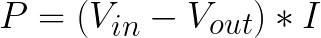
Where P is power in watts, Vin is the input voltage, Vout is the regulated output voltage, and I is the load current in amperes.
Worked Example 1: PT2399 Circuit
A 7805 is supplying a PT2399 from a 9V rail. The PT2399 draws approximately 30mA at 5V.


120mW is manageable. A TO-92 package (78L05) can handle this without a heat sink under normal conditions.
Worked Example 2: Microcontroller Circuit
A 7805 supplying a microcontroller draws 200mA from a 9V supply.


800mW in a small package will cause significant heat buildup. A TO-220 package with an appropriate heat sink is required at this power level.
Heat sink guidance: As a practical rule, plan for a heat sink when the calculated dissipation exceeds approximately 500mW. Above 1W, consider whether a linear regulator is the right choice for the application, or whether a switching regulator would be more thermally efficient. Also note: the larger the voltage gap between Vin and Vout, the more heat is generated at the same load current. Where possible, use the lowest supply voltage that still satisfies the dropout requirement.
Note: As a rule of thumb, if your circuit draws over, say, 20mA then you are advised to use a heat sink in order to dissipate the heat. There are kits available on Amazon or Tayda specifically for heat sinking 78xx components.
Fixed-Voltage Regulators
The 78xx family of fixed-voltage regulators is the standard starting point for DIY pedal designs requiring a regulated positive supply voltage. They are three-terminal devices (input, output, and ground) and require minimal external components to function.
The 78xx Naming Convention
The suffix after “78” directly encodes the output voltage. 7805 outputs 5V. 7809 outputs 9V. 7812 outputs 12V. The “L” variant (78L05, for example) denotes a low-power version in a TO-92 package, rated for 100mA rather than 1A. Use the L variant for low-current loads like the PT2399; use the standard TO-220 package for anything drawing more.
| Device | Output Voltage | Max Current | Package | Common Application |
|---|---|---|---|---|
| 7805 / 78L05 | 5V | 1A / 100mA | TO-220 / TO-92 | PT2399 delay circuits, 5V logic |
| 7809 | 9V | 1A | TO-220 | Regulated 9V sub-rail |
| 7812 | 12V | 1A | TO-220 | 12V sub-rail from higher supply |
| AMS1117-3.3 | 3.3V | 800 mA | SOT-223 | ESP32, STM32, RP2040, ARM MCUs |
| LD1117-3.3 | 3.3V | 800 mA | TO-220 / SOT-223 | ARM MCUs, 3.3V digital ICs |
| LD1117-5 | 5V | 800 mA | TO-220 / SOT-223 | Higher-current 5V LDO applications |
Fixed Regulator Circuit
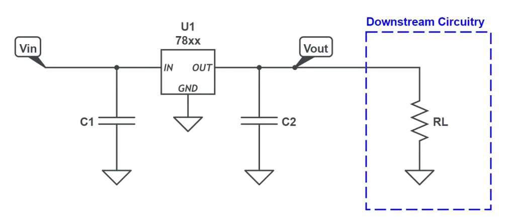
The circuit requires only two capacitors beyond the regulator itself. C1 on the input pin and C2 on the output pin stabilize the regulator and suppress oscillation. Typical values from the 7805 datasheet are 100µF on the input and 47µF on the output. For LDO regulators such as the AMS1117-3.3, the datasheet typically recommends smaller capacitors: 10µF is common on both input and output. Always check the specific datasheet for recommended values.
Note that the power supply filter from Circuit 8 (R1, C1, and D1) should still precede the regulator on the incoming supply rail. The regulator does not replace the filter; the filter cleans the rail before it reaches the regulator’s input.
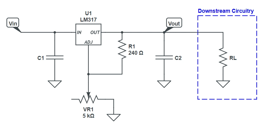
Adjustable-Voltage Regulators: The LM317
When the required output voltage does not match a standard fixed regulator, the LM317 adjustable regulator is the practical solution. It covers output voltages from 1.25V to 37V and is available in TO-220 and TO-92 packages.
Like the 78xx family, the LM317 is a three-terminal device, but instead of a ground pin, it has an adjustment pin (ADJ). The output voltage is set by a resistor divider connected between the output pin and the adjustment pin. The LM317 maintains a fixed 1.25V reference voltage between its output and adjustment pins. The resistor divider uses that reference to set the final output voltage.
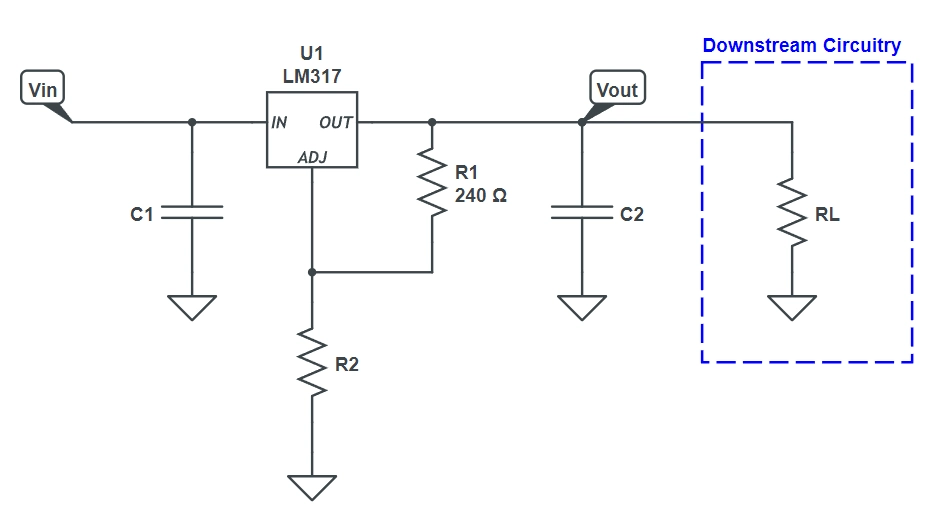
LM317 Output Voltage Formula
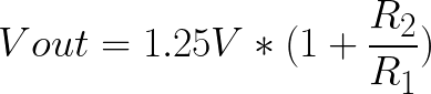
R1 is typically fixed at 240Ω, which is a value chosen to ensure the LM317’s minimum load current requirement is met. R2 is selected to achieve the desired output voltage.
Worked Example: Setting 5V Output
5V = 1.25V × (1 + R2 / 240Ω) 4 = 1 + R2 / 240Ω 3 = R2 / 240Ω R2 = 720Ω → use 750Ω (nearest standard E24 value)
With R1 = 240Ω and R2 = 750Ω, the actual output voltage is:
Vout = 1.25V × (1 + 750 / 240) = 1.25V × 4.125 = 5.16V
5.16V is within acceptable tolerance for the PT2399 and most 5V digital logic. For applications requiring tighter precision, adjust R2 accordingly or substitute a trimpot for R2 to allow fine adjustment on the bench.
LM317 Calculator: Use the Stompbox Electronics LM317 Calculator to find R1 and R2 values for any target output voltage without manual calculation.
Choosing the Right Regulator for Your Design
A four-step process covers the decision for most DIY pedal design scenarios.
- What voltage does the component need? Find the supply voltage specification in the datasheet of the IC or module being powered. Note whether it requires a single voltage or a range.
- Does the dropout voltage work with your supply? Subtract Vout from Vin. If the result exceeds the regulator’s dropout voltage specification by a comfortable margin, the regulator will function correctly. If the margin is tight (particularly in battery-powered designs where Vin will fall over time) select an LDO regulator.
- How much current will the load draw? Sum the quiescent current from the datasheets of all components on the regulated rail. Calculate heat dissipation using P = (Vin − Vout) × I. Determine whether a heat sink is needed.
- Is the required output a standard fixed voltage? If yes, use a fixed 78xx or LDO device. If the required voltage is non-standard or needs to be adjustable during development, use the LM317 with appropriate resistors or a trimpot.
Common case summary: PT2399 delay circuit from 9V supply → use 78L05 (TO-92, 100mA). Modern ARM microcontroller from 9V supply → use AMS1117-3.3 (SOT-223, 800mA). Non-standard output voltage → use LM317 with calculated R1/R2.
Component Reference
The following components cover the linear regulator requirements for the most common DIY pedal design scenarios.
| Component | Value / Type | Purpose |
|---|---|---|
| 78L05 | 5V, 100mA, TO-92 | Fixed 5V for PT2399 and low-current 5V loads |
| 7805 | 5V, 1A, TO-220 | Fixed 5V for higher-current 5V loads |
| AMS1117-3.3 | 3.3V, 800mA, SOT-223 | Fixed 3.3V for ARM microcontrollers (ESP32, STM32, RP2040) |
| LM317 | 1.25 – 37V adjustable, 1.5A, TO-220 | Adjustable output for non-standard voltages |
| C1 (input cap) | 100uF electrolytic (78xx) / 10uF (LDO) | Stabilizes regulator output |
| C2 (output cap) | 47uF electrolytic (78xx) / 10uF (LDO) | Stabilizes regulator output |
| R1 (LM317) | 240Ω (1/4W) | LM317 reference resistor (fixed) |
| R2 (LM317) | Calculated per Vout or trimpot | LM317 output voltage setting |
| Heat sink | TO-220 compatible | Required when P dissipation exceeds ~500mW |
Resources
[1] Stompbox Electronics LM317 Calculator – Calculate R1 and R2 values for any LM317 output voltage target.
[2] Valve Wizard Small Time Schematic – A well-documented PT2399 delay design showing the 78L05 regulator in context.
[3] 78xx Series – Wikipedia – Full 78xx family reference including output voltages and package types.
[4] Circuit 8 of 48: The Power Supply – The power supply filter (R1, C1, C2, D1) precedes the linear regulator in the power stage.
Guitar Effects Design in 48 Circuits or Less
This post is part of the 48 Circuits or Less series by Stompbox Electronics. Each installment covers one fundamental pedal circuit building block – concept, demonstration, and supplemental resources.
View more articles in this series here.
Meet the Author:

Hi, I’m Dominic. By day, I’m an engineer. By night, I repair and modify guitar effects! Since 2017, I’ve been independently modifying and repairing guitar effects and audio equipment under Mimmotronics Effects in Western New York. After coming out with a series of guitar effects development boards, I decided the next step is to support that community through content on what I’ve learned through the years. Writing about electronics gives me great joy, particularly because I love seeing what others do with the knowledge they gain about guitar effects and audio circuits. Feel free to reach out using the contact form!
The Tools I Use
As a member of Amazon Associates, Stompbox Electronics earns and is supported by qualifying purchases.


