In this article, I go through each of the TS9DX Modes and give an analysis on how they alter the Tubescreamer clipping circuit. For each Mode, I show the clipping circuit, the waveforms they produce, and a plot of their frequency response (tonal characteristic).
As a member of the Reverb Partner Program and as an Amazon Associate, StompboxElectronics earns from, and is supported by, qualifying purchases.
Disclaimer: Stompbox Electronics and/or the author of this article is/are not responsible for any mishaps that occur as a result of applying this content.
The Ibanez TS9DX Modes – An Introduction
The TS9DX has all the same workings of a TS-9 with the addition of a 4-position Mode knob, allowing the user to select between four separate circuit configurations:
- TS-9 Mode
- + (Plus) Mode
- Hot Mode
- Turbo Mode
This post covers the workings of each of these four Mode configurations and shows the relative differences between each of them. First we’ll remind ourselves of the TS-9 circuit, which the TS-9DX is based on. After that, we’ll go through the sonic and hardware differences between each Mode.
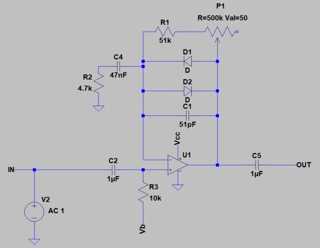
Before diving into the Mode settings it would help to know how the Drive control in the Tubescreamer ticks. Figure 1 (below) is a reminder of the original TS-9 drive circuit and serves as a foundation on which we can understand the other Mode configurations.
In the article, An Analysis of the Ibanez TS-9 Clipping Circuit, we covered two main areas:
- How diodes D1 and D2 affect the clipping characteristic
- How C4 imposes a frequency-dependent gain response
The TS-9DX basically modifies these two areas of the circuit to produce four variations to choose from.
Mode #1: TS9 Mode
The first of the four Modes involves the components utilized in the original TS9 Tube Screamer model. The other three modes only apply changes to (1) the clipping diode structure and (2) the frequency-dependent gain.
TS9 Mode Clipping Circuit Schematic
I’ll use this schematic as a baseline model and show the transient response (Figure 2A) and the frequency response (Figure 2B) for each Mode.
TS9 Mode Transient Response
The transient response gives us an idea for how the circuit responds to changes in input amplitude (i.e. your guitar volume or pick attack.)
The following plots are made using fixed input frequency of 750 Hz. The input signal amplitudes used, from least to greatest, are 1mV, 2mV, 4mV, 8mV, 10mV, 25mV, 50mV and 100mV. They correspond to each of the traces in the plot below.

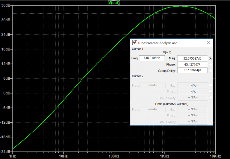
TS9 Mode Frequency Response
The frequency response shows us the gain achieved across a range of frequencies. With this, we can see how changes in C4 will affect the output tone of the Drive circuit, which can give you a good idea about what you’ll hear at the output of the pedal.
For the TS9 Mode, the high-pass cut-off frequency ends up being 615 Hz with C4 at 47nF.
Mode #2: + Mode
The second mode, labelled “+,” adds in two more clipping diodes, each in series with the existing ones. The 47nF capacitor also increases more than 5x its value to an electrolytic 0.22uF cap.
+ Mode Clipping Circuit Schematic
Figure 3 shows the circuit configuration for the + Mode. Note how D3 and D4 were added to the feedback path and that C4 has been replaced by a 0.22uF capacitor.
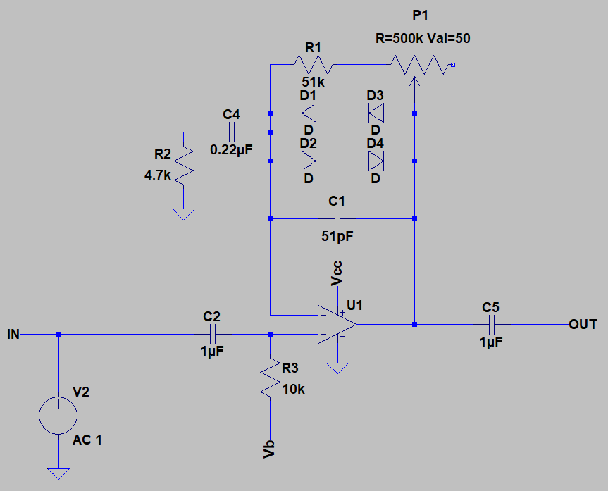
The silicon diode has a forward voltage drop that is roughly 0.6V – 0.7V. Placing two in series doubles the voltage drop to 1.2V – 1.4V. This increases the threshold at which the drive circuit begins clipping, causing less compression, less harmonic distortion, and more volume.
+ Mode Transient Response
With the transient response, the sine wave does not distort until the 6th largest input signal (the yellow trace) is applied. Before, in Figure 2A, the drive circuit started to clip after just the 3rd largest input signal. Also note how the Drive circuit’s output amplitude range has increased from ~600mV to ~1.2V, resulting in more volume.

+ Mode Frequency Response
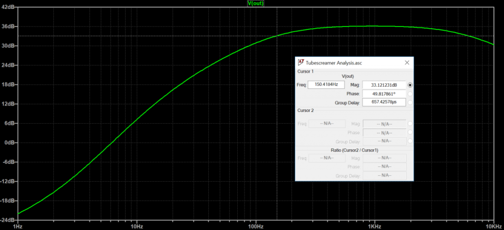
The increase in C4 from 47nF to 0.22uF results in a down-shifted cut-off frequency from 615 Hz to approximately 150.4 Hz (Figure 4B). This allows for more gain in the low-end frequency range. Ibanez also switched the capacitor type from metal-film to electrolytic. Since this capacitor isn’t directly in the signal path, the material is not too concerning.
Mode #3: Hot Mode
Since LEDs are technically diodes they can be used in much the same way as the silicon diodes from the previous modes.
Hot Mode Clipping Circuit Schematic
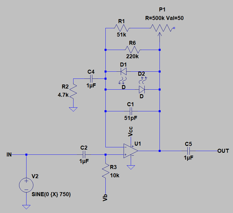
For the “HOT” mode the TS-9DX swaps out all the silicon diodes and replaces them with two red LEDs. A resistor is placed in parallel with these LEDs, which acts to reduce the overall gain of this mode.
Hot Mode Transient Response
The transient response is very similar to that of the TS9 mode, and I’m not entirely trusting of LTSPICE’s LED model in this application, so I’ve opted to not post the transient response plot.
Hot Mode Frequency Response
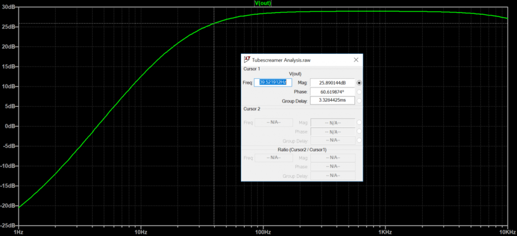
The frequency response is shown in Figure 6. The cut-off has decreased to ~40Hz due to C4 increasing to 1uF, which allows for more gain to enter the low-end response.
With that said, the gain is actually lower than that of previous modes. The overall achievable gain has been reduced by introducing R6 to the feedback path. The exact value of this resistance is not known to me, but it’s effect is to essentially reduce the gain.
Mode #4: Turbo Mode
Finally we have Turbo mode! In Turbo mode a loud, boosted signal is achieved, thanks to the removal of all diodes in the clipping circuit.
Turbo Mode Clipping Circuit Schematic
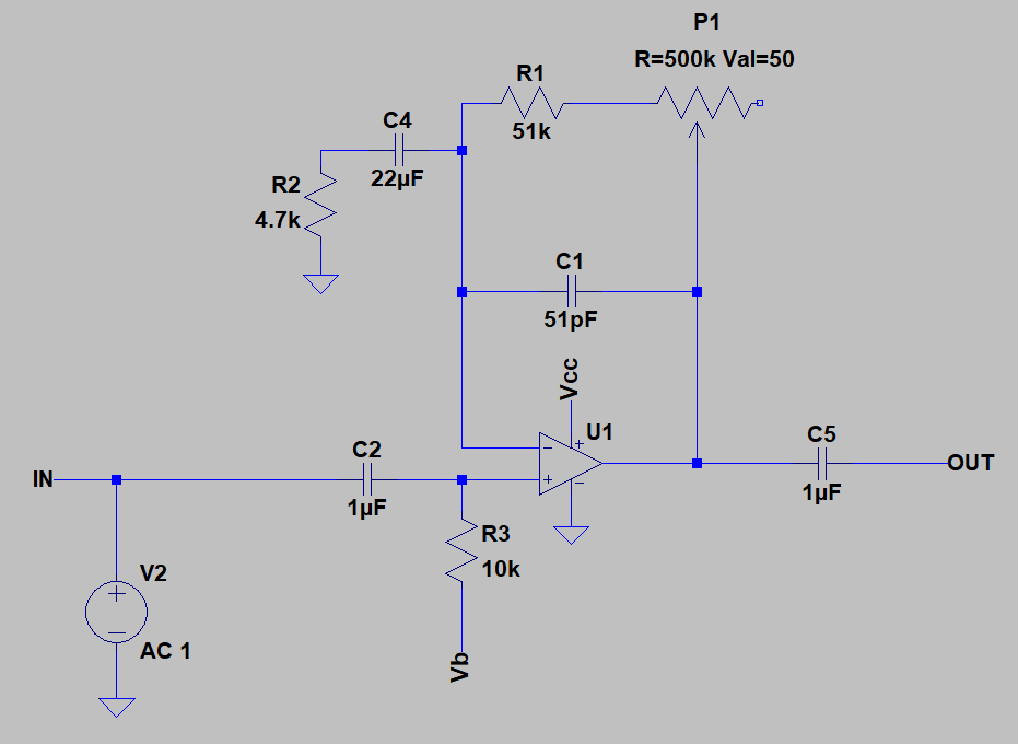
Turbo mode eliminates all the clipping diodes (Figure 7), thus allowing the output signal the freedom to swing at a much larger amplitude. This results in the highest amount of volume offered by any of the TS-9DX modes, as shown in Figure 8A.
Turbo Mode Transient Response
Since the diodes are out of the circuit the only device that can provide any sort of clipping is the op amp itself. The input signal is biased to 4.5V (Vb) and the op amp is powered by a single supply of 9V (Vcc). Theoretically, this allows 4.5V of head-room for the signal to swing, but in practice it’s a little less than that.
The transient signal below exhibits op amp distortion with the Drive maxed out.

Turbo Mode Frequency Response
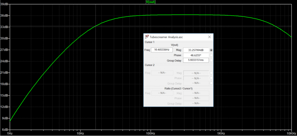
With Turbo mode comes an increase in the value of C4 up to 22uF. This shifts down the cut-off frequency to ~16.5 Hz, which essentially gives rise to all the bass you’ll ever need in a Tube Screamer. In fact, this mode would probably suit bass more-so than guitar!
Wrap-Up
There you have it, an Inside Look to the inner workings of the TS-9DX. Some interesting modification ideas can be extracted from this article, so please comment below if you’ve succeeded in finding a mod that fits your style!
See Electrosmash and Geofex for much more thorough deep dives into the Tubscreamer circuit.
Meet the Author:

Hi, I’m Dominic. By day, I’m an engineer. By night, I repair and modify guitar effects! Since 2017, I’ve been independently modifying and repairing guitar effects and audio equipment under Mimmotronics Effects in Western New York. After coming out with a series of guitar effects development boards, I decided the next step is to support that community through content on what I’ve learned through the years. Writing about electronics gives me great joy, particularly because I love seeing what others do with the knowledge they gain about guitar effects and audio circuits. Feel free to reach out using the contact form!
The Tools I Use
As a member of Amazon Associates, Stompbox Electronics earns and is supported by qualifying purchases.


