
In this article we’ll be diving into the inner workings of the TS-9 clipping circuit and peer into its method of operation one component at a time. First we’ll consider the basic skeleton upon which the Drive circuit is based – the non-inverting operational amplifier. From there we’ll exhibit the nuances of how the signal is filtered before finally diving into the Tube Screamer’s clipping characteristics.

As a member of the Reverb Partner Program, eBay Partner Network, and as an Amazon Associate, StompboxElectronics earns from, and is supported by, qualifying purchases.
Disclaimer: Stompbox Electronics and/or the author of this article is/are not responsible for any mishaps that occur as a result of applying this content.
The Ibanez TS-9: An Introduction
Scoring at one of the hottest pedals in the history of overdrives the Ibanez Tube Screamer lives up to it’s name. From the 808 to the re-issues, the Tube Screamer is regarded as one of the most popular overdrives on the market.
It’s most notable attribute is it’s ability to boost mids and send them straight into the tubes of an amplifier, preferably on the verge of break-up, cutting through the mix for lead lines and driving riffs. It’s gained such a cult following that even modern pedals have based their designs on it’s familiar, elementary drive circuit.
The TS-9 Clipping Circuit
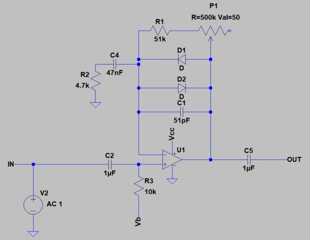
Figure 1 shows a model of the Tubescreamer clipping circuit. Our input signal is generated by the voltage source V2 and passes through C2 to the non-inverting input of U1 at a bias voltage, Vb, which is set to 4.5V. The output of the op amp runs through C5 to remove the DC component before it reaches the true output (OUT) of the circuit.
Non-Inverting Amplification
The drive circuit gets its character from the feedback network between the Inverting Input and the Output of the op amp. When we disregard D1, D2, C1, and C4 what we have is a simple non-inverting amplifier.
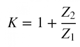
The gain is determined by Equation 1, where Z1 is equal to R2 and Z2 is equal to R1 in series with the in-circuit Drive pot resistance.
With the assumptions above, the gain of this circuit starts off at 11.85 (21.5dB) and maxes out at 118 (41.5dB).
Tube Screamer Gain Range: 11.85 to 118 (21.5 dB – 41.5 dB)
Frequency-Selective Gain
Now when we introduce the capacitor C4 it is in series with R2. The impedance of C4 is frequency-selective, so it lets higher frequency content through and blocks lower frequency content. In this way C4 and R2 form a high-pass branch with a cut-off frequency at approximately 720 Hz.
The gain values above are correct for frequencies above 720 Hz. For frequencies below 720 Hz the impedance of this branch gradually increases the value of Z1 in Equation 1. That, in turn, corresponds to a proportional decrease in gain.
Gain is mainly applied to frequencies above 720 Hz. Frequencies under 720 Hz are not as amplified.
So the Tube Screamer mainly applies gain to frequencies above 720 Hz. It applies a lesser amount of gain to bass frequencies.
Where, then, does the mid-range characteristic of the Tube Screamer come into play? Well, the circuit block directly after the drive circuit happens to be an active tone circuit incorporating a low-pass filter with a cut-off frequency at about 720 Hz. This produces a mid-range “hump” that accentuates the mid-frequency range of the Tube Screamer, producing it’s signature mid-range quality.
How the TS-9 Circuit Smooths High-Frequency Harmonics
Now let’s bring C1 into the picture. Being a capacitor, it’s impedance is also frequency-dependent. It passes high frequency content and blocks low frequency content. The exact amount of that frequency content is dependent on the parallel combination of C1 and the series resistance of R1 and P1.
In a parallel circuit the path with the least resistance passes the most signal. As the impedance of both branches come closer together the signal becomes more and more “shared” between the two paths.
The best way to illustrate this is with a plot. Figure 2, below, shows the frequency response of the drive circuit with zero resistance from the drive pot. The curve in Figure 3 describes the frequency response with the drive pot at maximum.
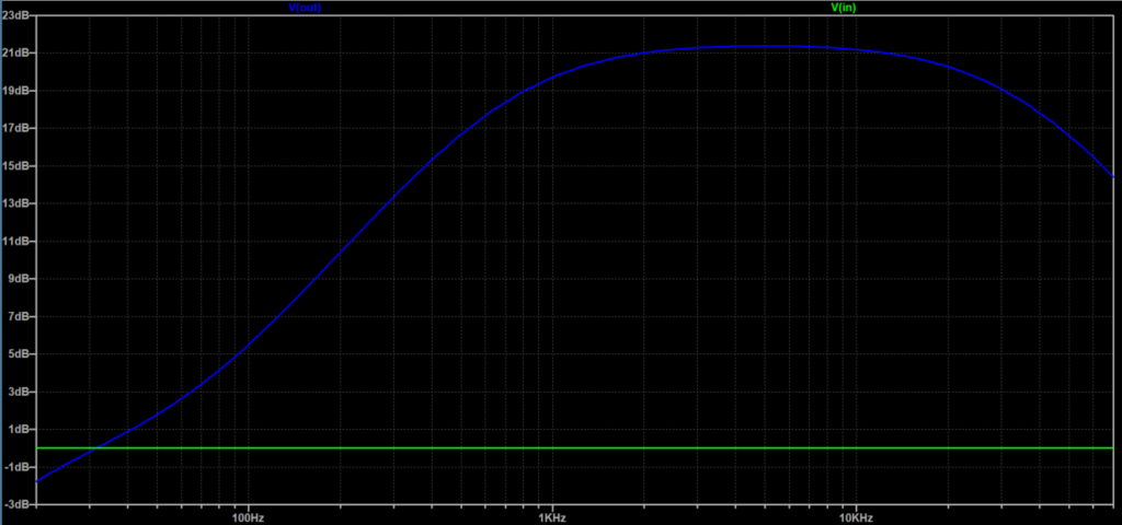
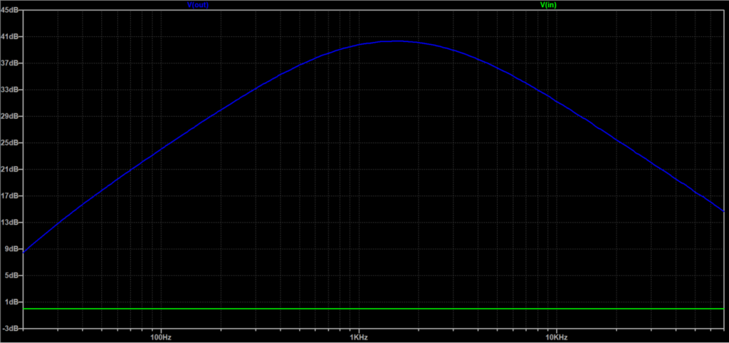
Now, turn your attention to the low-pass characteristic. In Figure 2 you can see that there is no low-pass roll-off within the audio band, since the signal starts to drop off at above 20kHz. In Figure 3, however, the signal starts dropping off between 2-3kHz. This effectively attenuates the high-frequency harmonics produced as the gain increases and as clipping takes place.
Soft Clipping in the TS-9 Drive Circuit
Diodes can be seen as one-way valves for current flow, but that’s not necessarily the entire picture. Diodes have a “turn on” voltage of roughly 0.6V to 0.7V (for silicon diodes). However, practical diodes can be observed to exhibit non-linearity at even lower voltages.
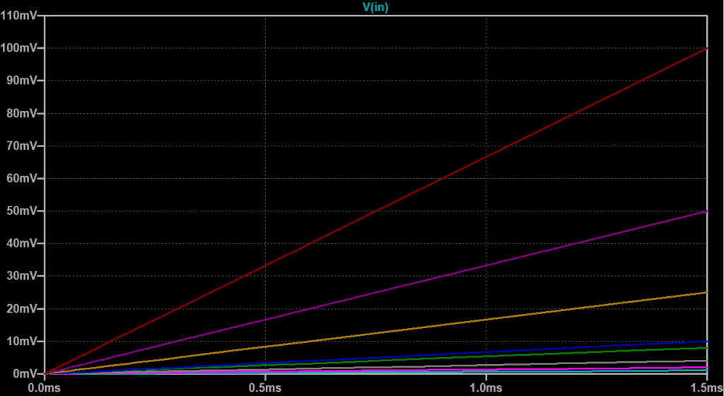
To demonstrate this, I’ve set up ramp signals of voltages ranging between 1mV and 100mV and I’ve applied them to the input of the drive circuit (Figure 4A). Figure 4B shows the output response to each input ramp.
Each response starts out linear, but each exhibits non-linearity when reaching about 200-250mV. This is because of the non-linear forward-bias resistance characteristic prior to the diode’s “turn-on” voltage of 0.6-0.7V.
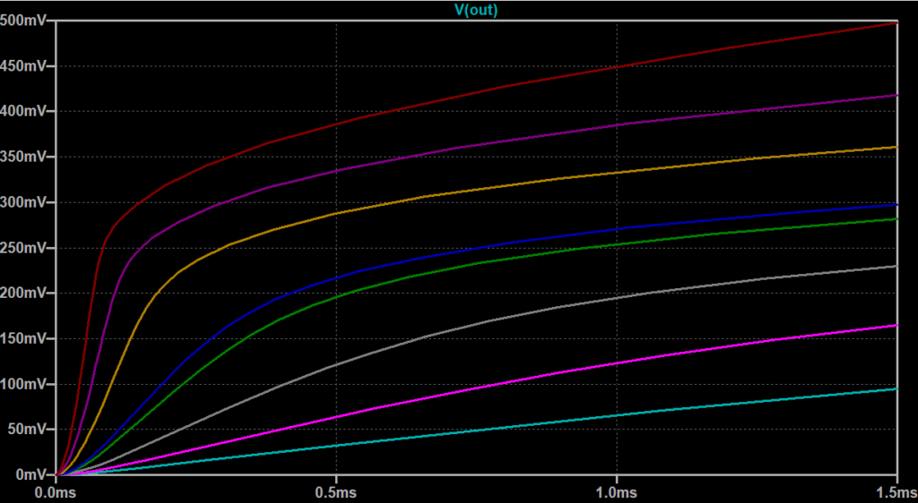
Note that the transition, while not linear, is still smooth. This is indicative of what’s called “soft clipping,” which is a characteristic that the Tube Screamer is known to have. Diodes, in conjunction with proper filtering, are responsible for producing these types of curves.
Forward Voltage Compression
One common complaint of the TS-9, and many other overdrives, is its “compressed” quality at high Drive settings. Take a look at Figure 5 below and take note of the amount of time it takes for the sine waves to transition from one polarity to the next.
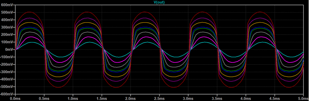
Now compare that with the amount of time the signals spend traveling within different voltage ranges. As the input signal level increases the transitions steepen, shortening the dynamic range of the signal. These observations alone constitute a less dynamic, compressed sound and results in a much more focused tone.
This is why many guitarists use a Tubescreamer to overdrive their amp instead of relying inherently on the pedal’s overdriven sound. The dynamic range and distortion characteristics within an amplifier are a lot different than that of a guitar pedal, with the amplifier circuit having the capability to produce a more desirable overdrive sound.
Wrap-Up
That’s it! We’ve covered the main topics related to the Tube Screamer drive circuit. Read even more about the inner workings of the Tube Screamer at Electrosmash or Geofex, as they go even further into the mechanisms behind the TS-808, TS-9, and other similar models.
Meet the Author:

Hi, I’m Dominic. By day, I’m an engineer. By night, I repair and modify guitar effects! Since 2017, I’ve been independently modifying and repairing guitar effects and audio equipment under Mimmotronics Effects in Western New York. After coming out with a series of guitar effects development boards, I decided the next step is to support that community through content on what I’ve learned through the years. Writing about electronics gives me great joy, particularly because I love seeing what others do with the knowledge they gain about guitar effects and audio circuits. Feel free to reach out using the contact form!
The Tools I Use
As a member of Amazon Associates, Stompbox Electronics earns and is supported by qualifying purchases.


