Today, we have a dead MXR Dyna Comp on the bench. The pedal turns on, as indicated by the LED. The output, however, is completely dead. Let’s figure it out!
As a member of the Reverb Partner Program and as an Amazon Associate, StompboxElectronics earns from, and is supported by, qualifying purchases.
Disclaimer: Stompbox Electronics and/or the author of this article is/are not responsible for any mishaps that occur as a result of applying this content.
MXR Dyna Comp Not Working
This week an MXR Dyna Comp compressor made it’s way to my bench. The client said that, after attempting to adjust the trimpot on the PCB, the Dyna Comp ceased to function. Even putting the trimpot back to it’s original settings could not bring the pedal back to life.
Troubleshooting the MXR Dyna Comp
Peeking inside the Dyna Comp reveals a CA3080 Operational Transconductance Amplifier (OTA) sitting just underneath the Sensitivity potentiometer. Bending the leads of the potentiometer a bit, I was able to stick a probe underneath and determine the voltage levels around the OTA. They all seemed to be biased correctly.
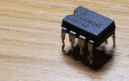
After verifying the OTA voltages, I went to look up a schematic and found the one hosted on Electro-Smash’s MXR Dyna Comp technical article to be particularly useful. The image below shows the location of the trim pot schematically, in relation to the OTA.
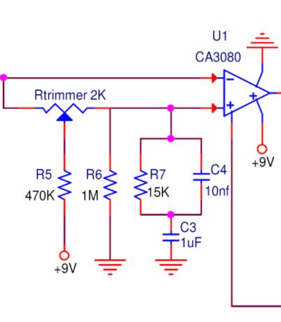
It’s possible that the adjustment of the trimpot caused a voltage differential between the OTA’s input terminals. That imbalance may have caused technical issues with the OTA chip. I attempted to adjust the trimpot back to the noon position, but the output was still silent.
At this point I wasn’t entirely sure it was the OTA. I decided to audio probe the circuit, following the input signal from the left side of the schematic. When I reached the OTA I noticed there was signal at the inputs, but zero output. After observing that, I was convinced the OTA was the culprit.
MXR DynaComp Repair
I didn’t have any spare CA3080s. Since the chips are somewhat difficult to source, I didn’t bother purchasing a replacement. Instead, I had a batch of LM13700 Dual OTA chips in my inventory. Since the CA3080 is a single-OTA chip, I only utilized one of the two OTAs in the LM13700.
There is one main technical difference between the CA3080 and the LM13700, and that is the diode bias pin housed on the LM13700. In this replacement, I simply left that pin disconnected.
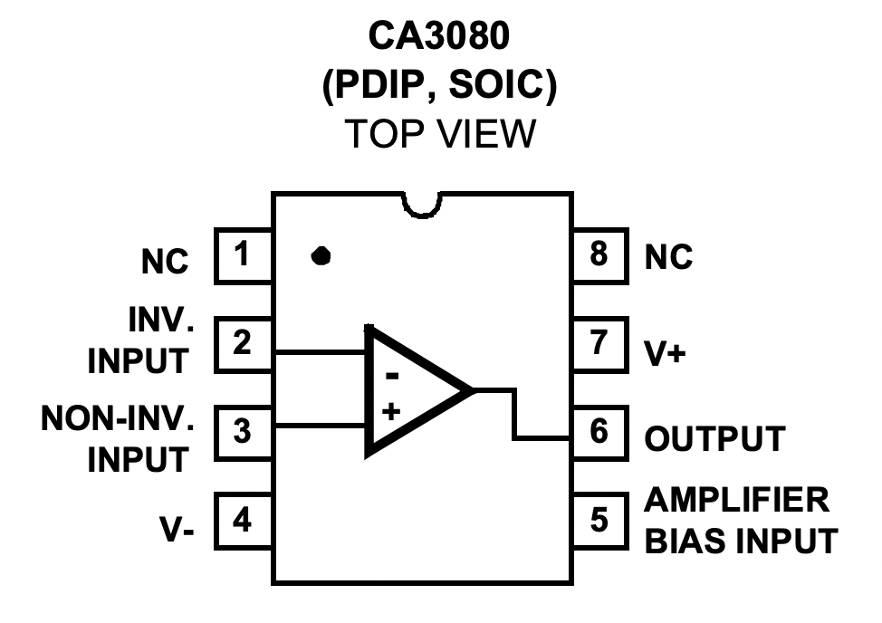
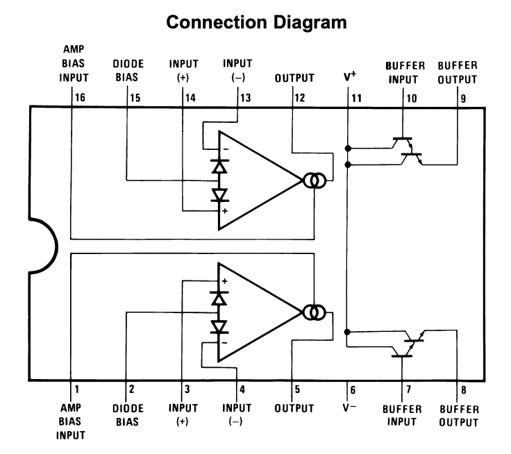
First, I mounted the LM13700 on a piece of vero-board. Then, I removed the CA3080 using a combination of hot-air soldering machine and a pair of anti-static tweezers.
Wiring the input terminals, output terminal, bias input, and power terminals were all that was needed to replace the CA3080 with the LM13700. After a quick test, the pedal was back in action!
Meet the Author:

Hi, I’m Dominic. By day, I’m an engineer. By night, I repair and modify guitar effects! Since 2017, I’ve been independently modifying and repairing guitar effects and audio equipment under Mimmotronics Effects in Western New York. After coming out with a series of guitar effects development boards, I decided the next step is to support that community through content on what I’ve learned through the years. Writing about electronics gives me great joy, particularly because I love seeing what others do with the knowledge they gain about guitar effects and audio circuits. Feel free to reach out using the contact form!
The Tools I Use
As a member of Amazon Associates, Stompbox Electronics earns and is supported by qualifying purchases.


