
This round of Repair Room features the 6-channel Furman HDS-6 Headphone Distribution System after a mild power surge incapacitated 5 of the 6 channels. In this post, I discuss what the HDS-6 system is, along with the process for how I fixed it.

As a member of the Reverb Partner Program, eBay Partner Network, and as an Amazon Associate, StompboxElectronics earns from, and is supported by, qualifying purchases.
Disclaimer: Stompbox Electronics and/or the author of this article is/are not responsible for any mishaps that occur as a result of applying this content.
The Furman HDS-6 Headphone Distribution System
The Furman HDS-6 utilizes Cat 5 cabling to distribute power and channel signals to remote units (HR-6’s). The remote units enable recording artist to monitor other tracks through a pair of headphones. They can be daisy-chained with other HR-6 units, helping the musician locally monitor tracks while recording.
The HDS-6 Circuit
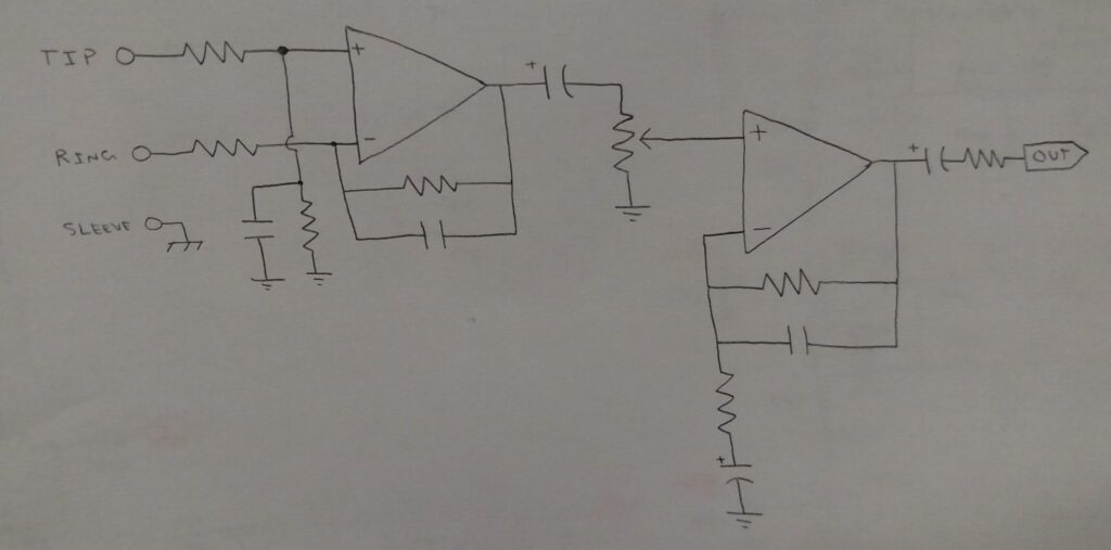
Luckily for us, the HDS-6 circuit isn’t too difficult. All inputs go through a couple non-inverting amplifiers before appearing at the Ethernet connector for distribution. Here’s a mock-up of the circuit for demo purposes:
A Note on Safety
An AC adapter plug powers the unit, which eventually converts to +/- 15Vdc using a couple voltage regulators.
That +/- 15Vdc split-rail powers all the op amps, which means there’s at least 30Vdc across each chip. With that, plus the 120VAC present in the box, you can seriously harm yourself if you’re not careful.
So if you’re reading this and thinking about repairing your own HDS-6, please follow all the applicable safety guidelines.
Troubleshooting the HDS-6
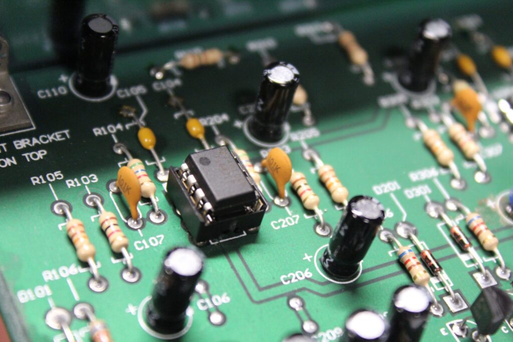
I opened up the chassis and, after some visual inspection, saw one of the capacitors had blown. I replaced that cap and powered the unit back up – still no good.
Other than that there was an odd white discoloration of the main board around one other capacitor. It didn’t seem to be an issue but I replaced that cap too for good measure.
I injected an audio signal into each of the channels and audio-probed the signal paths. For almost every channel the second op amp in the signal path wasn’t functioning, as confirmed by measuring the DC voltages on each op amp chip.
The table below shows the voltage measurements for the three dual op amp chips U101, U201 and U301:
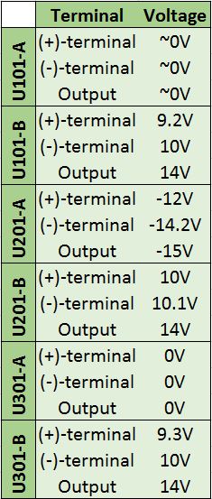
Usually op amps in an audio signal path are DC-biased to the reference voltage. In this particular circuit each op amp is powered by a split rail +/- 15Vdc, so the reference voltage is 0Vdc.
That means each op amp should be DC-biased to approximately 0V. The measurements above indicate that all three op amps (U101, U201, and U301) failed the test!
Repairing the Furman HDS-6
Since the issue clearly lies with the op amps, I had to replace them. I had a couple TL082s on-hand, and replacing them fixed the issue. The TL082 has an input noise voltage of 16nV/√Hz. But if available, I recommend a chip with a lower input noise voltage, like a NE5532.
As an Amazon Associate, Stompbox Electronics earns from, and is supported by, qualifying purchases.


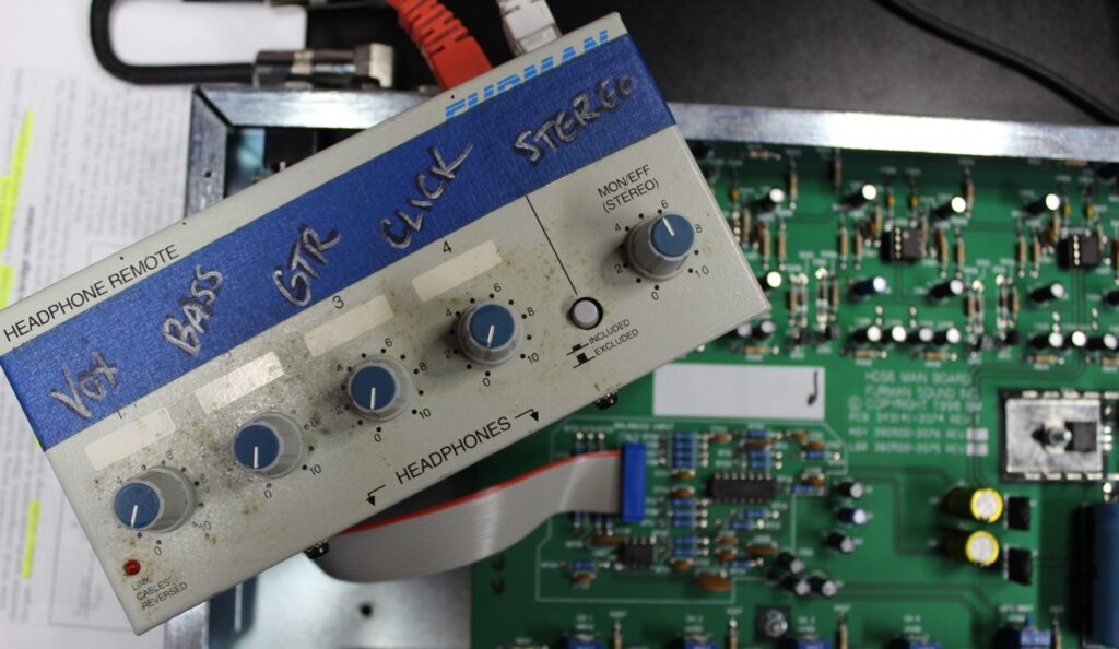
Testing HR-6 Units
I’ve had a few HR-6 units come in for a knob replacement, pot cleaning, and even an ethernet connector replacement. The enclosed ethernet connector makes it difficult to test these units, so I built this short visual guide for testing the HR-6 connections.
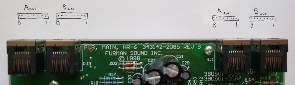
The Bin and Bout jacks route power to and from the HR-6. Pin 5 houses a +22V rail, pin 8 houses a -22V rail, and pins 4 and 7 are grounded.
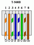
In order to test the HR-6, the +/- rails must be powered via a CAT5 cable. The cable I use is wired in 568-B fashion, which corresponds to the numbering scheme below. The numbers on the this diagram correspond to the numbering scheme up above.
Ports Bin and Bout hold the stereo signals. The “left” signal is located on pins 1 and 2, while the “right” signal is located on pins 3 and 6.
Lastly, ports Ain and Aout hold channels 1 through 4. Channels 1, 2, 3, and 4 are located on pins 1 & 2, 3 & 6, 4 & 5, and 7 & 8, respectively.
Meet the Author:

Hi, I’m Dominic. By day, I’m an engineer. By night, I repair and modify guitar effects! Since 2017, I’ve been independently modifying and repairing guitar effects and audio equipment under Mimmotronics Effects in Western New York. After coming out with a series of guitar effects development boards, I decided the next step is to support that community through content on what I’ve learned through the years. Writing about electronics gives me great joy, particularly because I love seeing what others do with the knowledge they gain about guitar effects and audio circuits. Feel free to reach out using the contact form!
Spotlight
This fix was done for DMS Productions located in Ransomville, NY!
The Tools I Use
As a member of Amazon Associates, Stompbox Electronics earns and is supported by qualifying purchases.


