

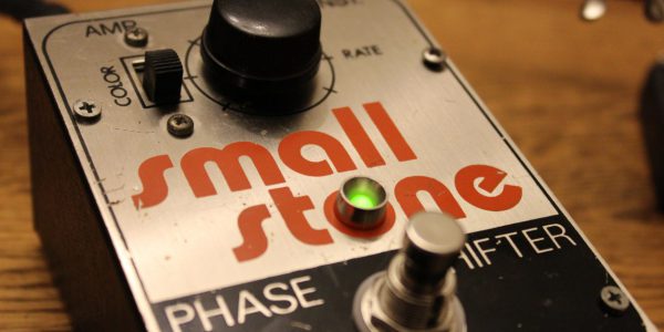
The Electro-Harmonix Small Stone Phase Shifter is a great addition to your board, with only one caveat…there’s no indicator LED! At least in the earlier vintage versions. In this day and age it’s almost a requirement to include this LED; but “back in the day,” when guitarists used just a handful of pedals, it wasn’t a necessity.
In this post I’m going to describe the EHX Small Stone True Bypass modification and how to install an indicator light, along with any problems that might occur along the way.

As a member of the Reverb Partner Program, eBay Partner Network, and as an Amazon Associate, StompboxElectronics earns from, and is supported by, qualifying purchases.
Disclaimer: Stompbox Electronics and/or the author of this article is/are not responsible for any mishaps that occur as a result of applying this content.
Mod Overview
The Small Stone I’m working on here is Version 2. The circuit board is marked “Issue J” and the schematic for it is provided at next.gr (contact me if link is broken).
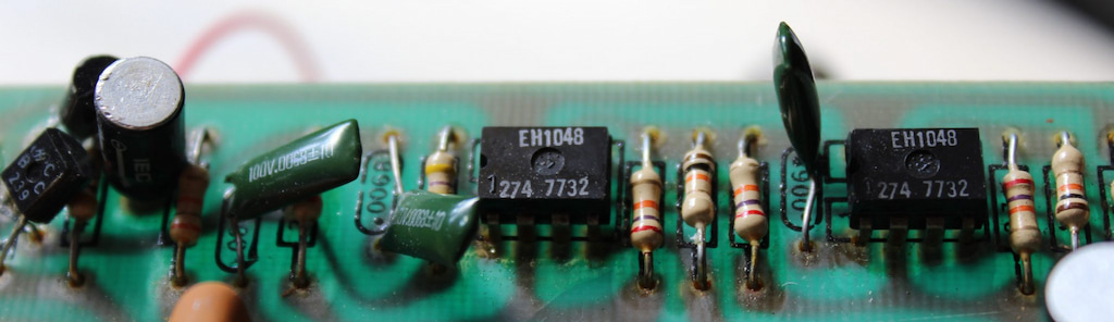
Something cool about this circuit: it sports a device called an Operational Transconductance Amplifier (OTA) – specifically, the EH1048. For those familiar with operational amplifiers (op amps), they are almost the same, except there are 2 additional pins to take into account for modulation.
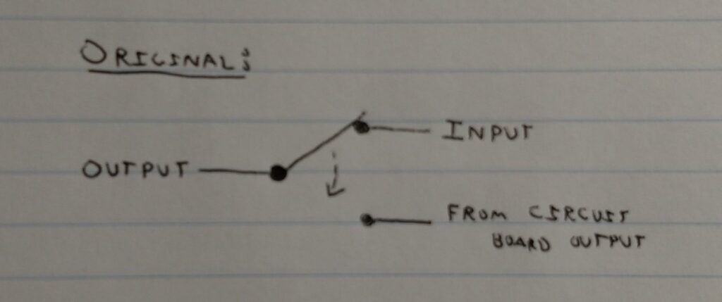
Out of the box, the Small Stone uses an SPDT footswitch to accomplish a “psuedo true bypass”. In bypass mode, the output is directly connected to the input signal. When engaging the effect, the switch connects the pedal output to the circuit board’s output.
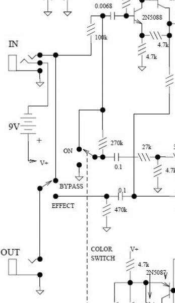
Looking at the schematic below, you can see that the input signal is always connected to the circuit board. This is “pseudo true bypass” because the switching only occurs by routing where the output comes from. There is no switching done on the input.
Small Stone Wiring Connections
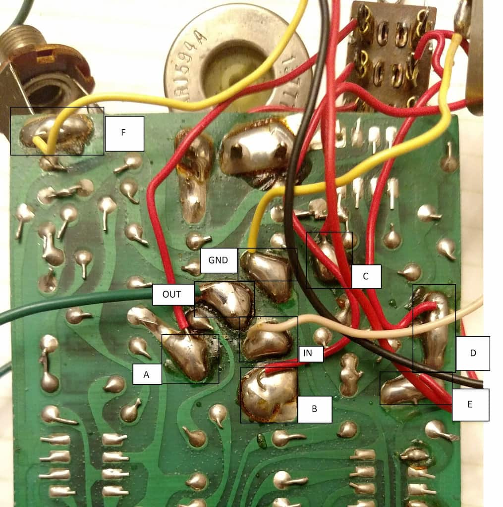
Before getting into the mods it helps to have a reference for which wire goes where. See below for a labeling scheme I made up for the circuit board wiring connections.
| Label | Description |
|---|---|
| A | Color Switch UP Position #1 |
| B | Color Switch COM Position #1 |
| C | Color Switch UP Position #2 |
| D | Color Switch COM Position #2 |
| E | Color Switch DOWN Position #2 |
| F | +9Vdc Power to circuit board |
| IN | Input connection to circuit board. |
| OUT | Effect output from circuit board. |
| GND | Ground connection of the circuit board. |
Adding an Indicator LED
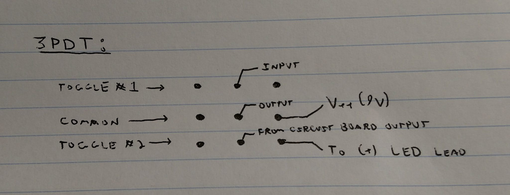
If your goal is to just install an indicator LED without changing the bypass method, then you only need a total of two poles and two throws. Therefore, you can use a DPDT or 3PDT switch to accomplish this. Since I only had 3PDT switches near me, I decided to use one of those.
You can see how I wired it in the mock-up below, which was fine for adding a simple indicator light. The middle pole does the actual switching while the right-most pole switches on and off the LED.
I recently stocked up on some LED holders and 5mm LEDs from LoveMySwitches, so I used those. You can also find them on Amazon:
As an Amazon Associate, Stompbox Electronics earns from, and is supported by, qualifying purchases.


The requested spot to drill was smack in the middle of the ‘O’ in “stone.” After taking the pedal off of the drill press I mounted the LED, added a 2.2k ohm resistor in series, soldered and heat-shrunk the leads, and tested out the finished installation. Worked like a charm!
The Small Stone True Bypass Mod
The idea here is to swap out the existing footswitch and use a 3PDT instead. That way, we can use standard 3PDT true bypass wiring, which will enable us to install an indicator LED and prevent tone suck on our bypass line.
See below for the standard way to wire 3PDT switches for True Bypass. The first set of lugs are used for routing the input signal. Another set of lugs are used for routing the output signal. The last set of lugs route the ON/OFF state of an indicator LED.
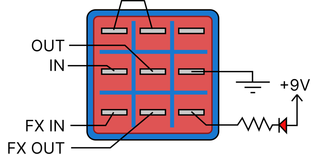
The power for the LED can be easily routed from the circuit board (9Vdc from point F above, ground connection to GND). The FX IN connects to the IN pad, while the FX OUT connects to the OUT pad. Connect the IN to the input guitar jack’s tip lug, and connect the OUT to the output guitar jack’s tip lug. Finally, bridge together the bypass lugs on the 3PDT as shown.
When you’re finished with the 3PDT True Bypass modification you may experience some switch pop. If that occurs, try adding a 1Meg ohm resistor between the input and ground.
For more on De-Popping a true bypass arrangement, see this post.
A Better 3PDT Wiring for the EHX Small Stone True Bypass Mod
The above method for 3PDT true bypass wiring is standard, but it could result in a “pop” sound when switching the Small Stone on or off. There is another wiring scheme you can try that grounds the circuit board’s input signal when not in use. See the wiring diagram below:
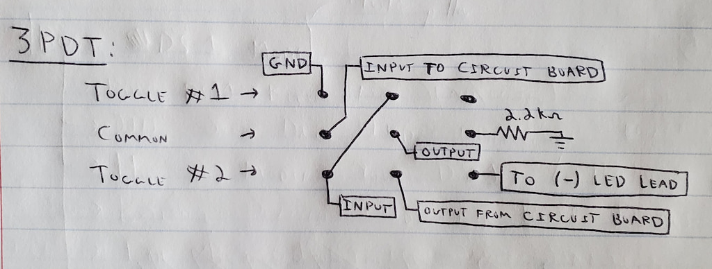
There are a few differences here:
- The LED is switched on the negative lead (cathode) instead of the positive lead. The bottom right lug connects the cathode of the LED. The anode connects directly to the 9Vdc source (point F in the photo above).
- A ground connection is made to the upper-left lug.
- There are two lugs that the tip lug of the input jack should be connected to: the bottom left and the middle top.
In bypass mode, the output connects directly to the input, just like before. In this case, though, the circuit board’s input connection is grounded.
When switching the pedal ON, the input signal will be routed to the circuit board’s input. The output signal will be taken from the output of the circuit board and the LED will pass current through the 2.2k resistor and illuminate.
This method illiminates the “pop” problem because it removes the possibility of charge build-up on the input of the circuit board. See Mr. Black’s “What really causes switch pop” article for more information.
Mounting Problems & Solutions
The circuit board itself is only supported by the shaft of the potentiometer being used to alter the phase rate. This forced the board to be mounted in close proximity to the cover. A small, rectangular piece of foam supported the bottom portion of the circuit board for further support and to ensure the board doesn’t short out against the bottom of the enclosure.
This support system provided a small problem. The 3PDT switch was taller than the stock switch. Because of that, the bottom lugs of the switch could easily short out against the circuit board.
To get around this I ended up cutting the rectangular foam piece holding up the bottom end of the circuit board. Shaving off about 3/4 of it provided enough leeway to (carefully!!) bend the potentiometer leads so as to angle the circuit board downwards from the knob. This provided enough space to mount the 3PDT switch.
As an added measure, I electrically isolated the lugs of the 3PDT switch using one-sided electrical tape and soldered all wires from the lugs such that none of them could push downwards and puncture through the tape.
Meet the Author:

Hi, I’m Dominic. By day, I’m an engineer. By night, I repair and modify guitar effects! Since 2017, I’ve been independently modifying and repairing guitar effects and audio equipment under Mimmotronics Effects in Western New York. After coming out with a series of guitar effects development boards, I decided the next step is to support that community through content on what I’ve learned through the years. Writing about electronics gives me great joy, particularly because I love seeing what others do with the knowledge they gain about guitar effects and audio circuits. Feel free to reach out using the contact form!
Spotlight
This mod was initially done for Deadwolf, Buffalo’s very own psychedelic rock band. Check it:
You can find Deadwolf on Facebook and Soundcloud!
The Tools I Use
As a member of Amazon Associates, Stompbox Electronics earns and is supported by qualifying purchases.


