Audio probing guitar effects circuits is an essential skill for the stompbox designer, repair person, and modder. An audio probe is a device used for detecting audio signals at specific points in a circuit. It is especially used to troubleshoot guitar effects circuits, and you can build one using just a few components.
In this post, you’ll learn all you need about audio probes, how to build one, and how to use them for different situations.
As a member of the Reverb Partner Program and as an Amazon Associate, StompboxElectronics earns from, and is supported by, qualifying purchases.
Disclaimer: Stompbox Electronics and/or the author of this article is/are not responsible for any mishaps that occur as a result of applying this content.
What are audio probes?
An audio probe is a simple device used to detect audio signals in a circuit. They are typically built using a handful of components, including a capacitor, a jack, a few pieces of hookup wire, and a couple alligator clips. Here’s an example of a homemade audio probe:
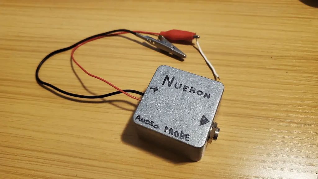
The two wires sticking out of the left side are for detecting the audio signal. The red wire is the signal wire and the black wire connects to ground.
The signal wire connects to the tip of the 1/4″ jack to the right. The ground wire connects to the sleeve of the 1/4″ jack. A typical instrument cable is used to connect between the audio probe and an amplifier. In this way, you can detect audio signals by simply “probing” around a circuit board.
Who needs an audio probe, anyway?
Repair technicians need audio probes to check where an audio signal is flowing properly through a circuit board. Whether your repairing guitar pedals, amplifiers, or other audio equipment, audio probing will help verify the signal flow.
If an op amp is fried, or if there are any cold solder joints, audio probing the circuit will help the technician figure that out.
DIY enthusiasts who build their own effects pedals often run into the problem of a newly built pedal not passing signal. Audio probes are perfect for this problem. Every DIY stompbox enthusiast needs an audio probe on hand.
How to use an audio probe
First, connect the ground wire to the enclosure of the guitar pedal using an alligator clip. This will make a proper ground connection and will ensure no excessive noise from improper grounding makes its way into the amplifier.
Next, connect the audio probe to the amplifier using a typical 1/4″ guitar cable.
Finally, apply power to the guitar pedal and probe it using the signal wire. The details from here on differ between whether you’re trying to troubleshoot a guitar pedal or whether you’re trying to modify it.
A Guide for Building Your Own Audio Probe
Materials
| Part | Quantity | Recommended Source |
|---|---|---|
| Capacitor, anything from 100nF to 1uF | 1 | Amazon | Tayda |
| Jack, 1/4″ Panel-Mount | 1 | Amazon | Tayda | Mouser |
| Enclosure | 1 | Amazon | PedalPartsPlus |
| Alligator Clips | 2 | Amazon |
| Hookup Wire | As Needed | Amazon |
Instructions
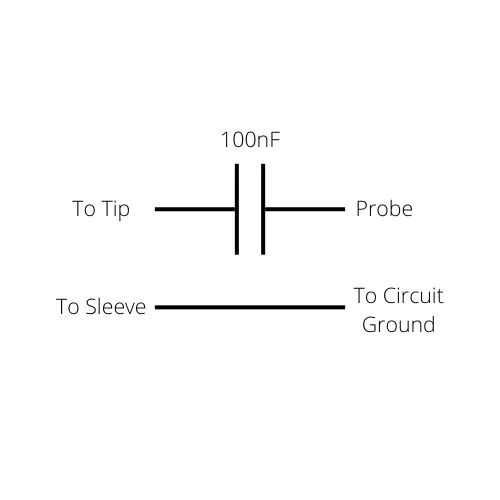
- Solder one leg of the capacitor to the tip of the 1/4″ jack.
- Solder a black wire to the sleeve of the 1/4″ jack.
- The other end of the black wire should be soldered to an alligator clip and used to connect to the circuit ground.
- Solder a red wire to the other leg of the capacitor.
- The other end of the red wire shoule be soldered to an alligator clip and used to probe the circuit.
Using an Audio Probe to Troubleshoot Guitar Effects
The primary use of an audio probe is to troubleshoot guitar effects that aren’t working correctly. There are at least three problems that can be detected using an audio probe:
- Faulty Components
- Cold Solder Joints
- Compromised Copper Pads & Traces
There is only one skill you need to master to find these problems – following signal flow.
Following Signal Flow Using an Audio Probe
The first step is to figure out where the signal is supposed to be traveling through on the circuit board. Once you have an idea of where to expect the signal, you can use an audio probe to figure out where the signal is dropping out, which will hopefully give you enough information to fix the issue.
By far the easiest way to start this process is to locate a schematic and trace out the signal path. Below is an example of a BOSS DS-1 schematic with the signal flow traced out in green.
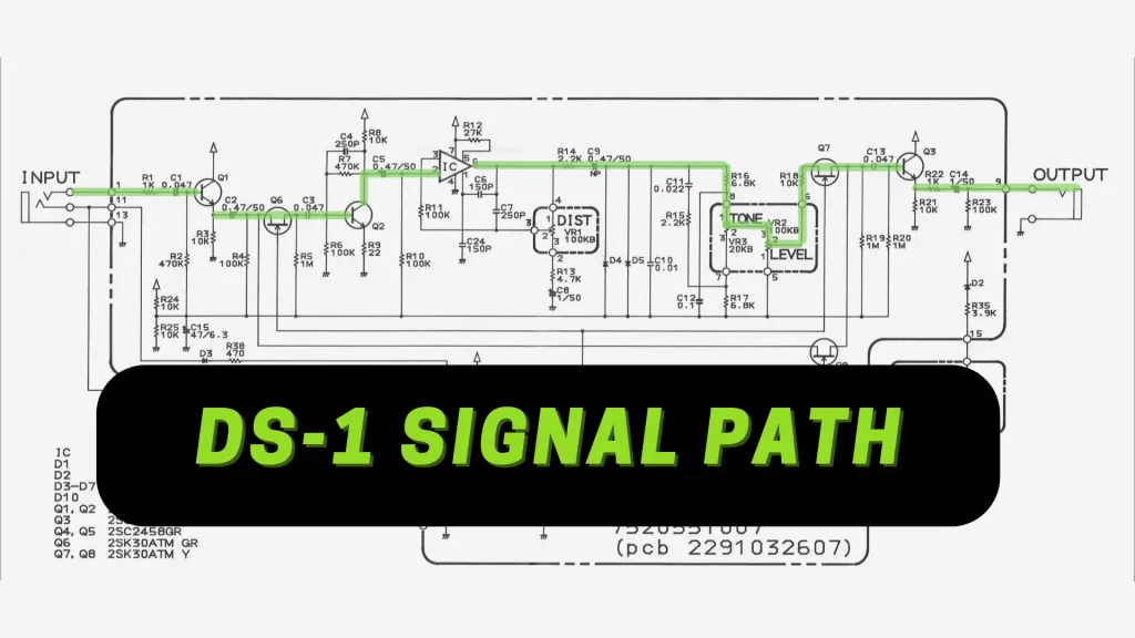
The idea is to probe along the green trace to figure out (1) whether a signal is present and (2) how it sounds at that point in the circuit. With this information you will be able to locate faulty parts and problems with the integrity of the copper traces and solder joints.
Use a Looper Pedal as a Test Signal
When you start audio probing you might quickly realize that going between strumming your guitar and probing the pedal is a demanding task. It’s very difficult to go back and forth between strumming the guitar, then to probing the circuit before the sound decays, back to strumming, back to probing, etc.
The best way to generate an audio source for probing guitar effects is to use a looper pedal. Capture a bit of your guitar playing, then replay it on a never-ending loop into the guitar pedal’s input.
Here are a few budget options for guitar pedal loopers:
Of course, you don’t necessarily need a looper pedal to do this. You can also use an old iPod playing MP3s, or you can use an AUX cord from a device that outputs audio.
Here’s a great Neo Soul backing track you can use through an AUX cord. If you need a 1/4″ to 3.5mm (1/8″) adapter, here are a few recommendations:
- Male 1/4″ to Female 3.5mm Adapter
- Male 1/4″ to Female 3.5mm Adapter in 1 ft, 5 ft, and 11.5 ft
- Male 1/4″ to Male 3.5mm Adapter in 4 ft, 10 ft, and 20 ft
- Male 3.5mm to Male 3.5mm Aux Cable, multiple lengths
- iPhone Lightning Plug-Compatible 3.5mm Adapter Cable
Using the PROTIS 1 Dual Jacks Module as an Audio Probe
The PROTIS 1 Guitar Effects Development Board simplifies the breadboarding experience by including two 1/4″ audio jacks: one for guitar input and another as an output to the amplifier.
At times, you might want to add a little more features like stereo, 1/4″ MIDI, control voltage input/output, or expression pedal input.
The PROTIS 1 Dual Jacks Module was designed with these feature extensions in mind and allows for that possibility in the prototyping phase.
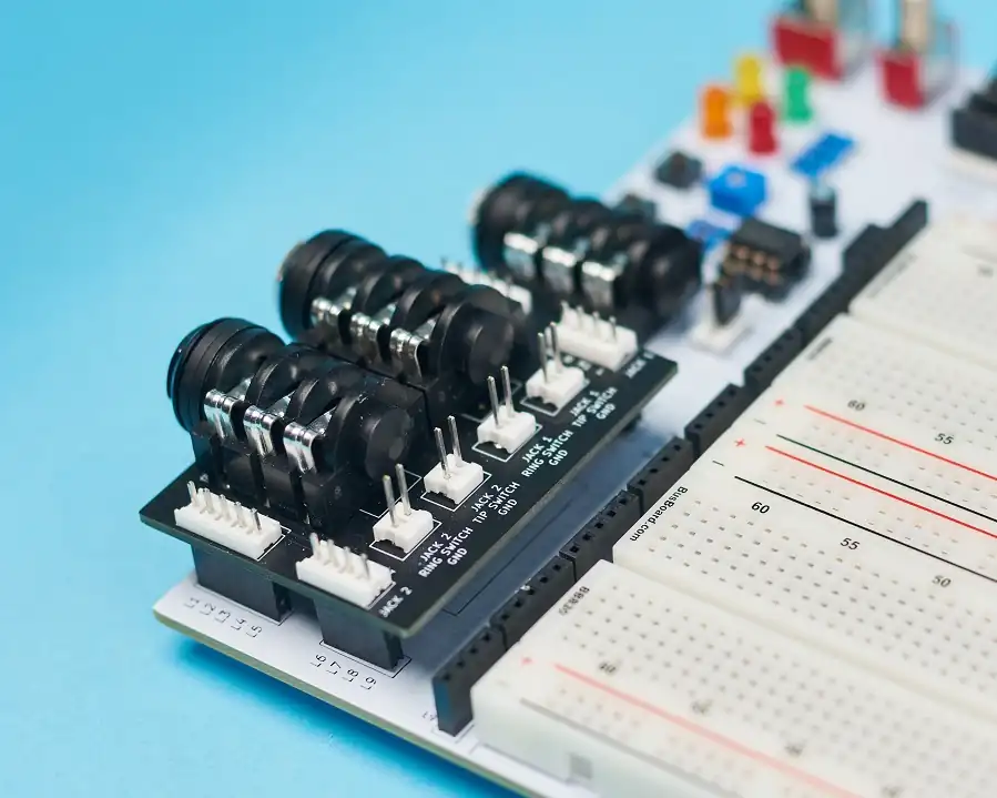
The module comes with an additional two 1/4″ guitar jacks.
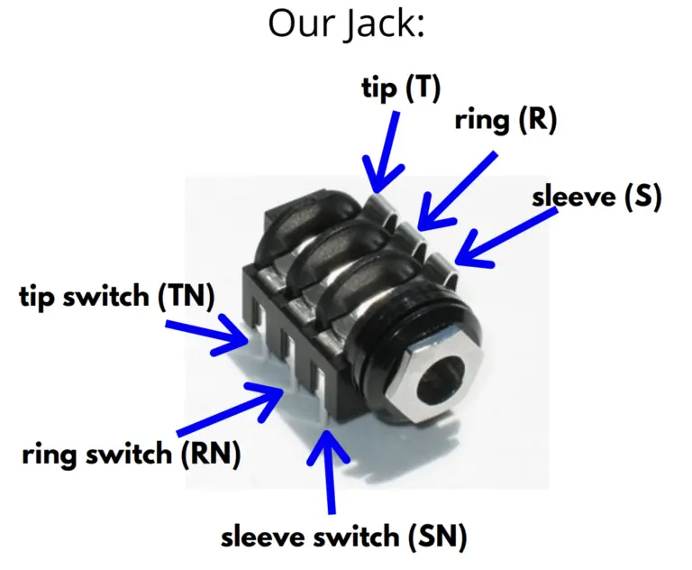
The tip (T) and ring (R) connections are available for use, along with their switch counterparts (TN and RN). The sleeve connections (S, SN) are connected to a terminal labelled GND. You must manually connect this ground to the PROTIS 1 board’s ground.
Audio Probing Guitar Effects with the Dual Jacks Module
Audio probing guitar effects circuits is easy with the Dual Jacks Module. Any one of the two jacks can serve as your audio probe jack, so let’s choose Jack 1.
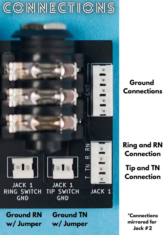
First, insert the module and remember to ground it to your circuit using a male-to-male breadboard jumper wire.
Next, find an empty and unconnected strip on the breadboard. Port over the tip connection of Jack 1 from the module to the empty strip using a jumper wire.
Then, insert the capacitor into the breadboard by connecting one lead to the tip and the other to a second empty, unconnected strip. Connect another jumper wire to that second cap lead and use it as the audio probe.
In the conventional way to build an audio probe (detailed above) you had loose wires to contend with while probing the circuit. At any given point the wires may disconnect or short against each other, distracting from the task at hand. Using the Dual Jacks module eliminates this issue.
We got rid of one problem, but what about the noise issue? Use one of the 2.54mm jumpers available on the PROTIS 1 board to shunt the two pins labelled “Tip Switch GND.” This connects the tip lug to ground, which silences the output of the audio probe.
Meet the Author:

Hi, I’m Dominic. By day, I’m an engineer. By night, I repair and modify guitar effects! Since 2017, I’ve been independently modifying and repairing guitar effects and audio equipment under Mimmotronics Effects in Western New York. After coming out with a series of guitar effects development boards, I decided the next step is to support that community through content on what I’ve learned through the years. Writing about electronics gives me great joy, particularly because I love seeing what others do with the knowledge they gain about guitar effects and audio circuits. Feel free to reach out using the contact form!
The Tools I Use
As a member of Amazon Associates, Stompbox Electronics earns and is supported by qualifying purchases.


