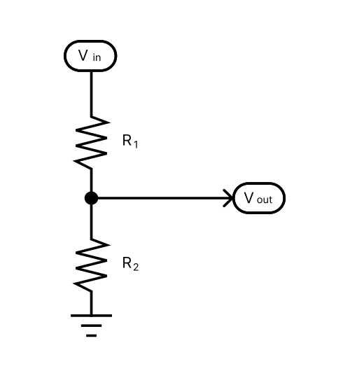
Voltage In (Vin):
Resistor R1:
Resistor R2:
Voltage Out (Vout):
Using the Voltage Divider Tool
To effectively use the Voltage Divider calculator, select which value you would like to calculate using the “Value to calculate” dropdown. This reveals 4 options:
- Voltage Out
- Resistor R1
- Resistor R2, and
- Voltage In
For the value you want calculated simply leave the box blank. Then, enter the three other known values. Finally, click “Calculate.” The answer will appear in the appropriate box.
For example, if I want to calculate the output voltage of a voltage divider then I would enter the known input voltage and the two resistor values into the Voltage In, R1, and R2 fields, respectively. Clicking “Calculate” yields the result in the Voltage Out field.
Calculating Output Voltage
For calculating the output voltage of a voltage divider, use the standard voltage divider equation. That is, take the resistance R2 and divide it by the sum of both resistors (R1+R2). Multiply the result by the input voltage and you’ll have calculated the output voltage of the divider.

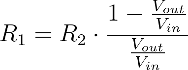
Calculating Resistor R1
The required resistance for R1 can be calculated using the following equation, derived from the standard voltage divider equation above.

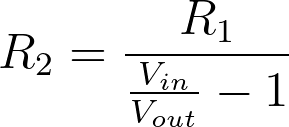
Calculating Resistor R2
The resistance for R2 is calculated using the following equation. Again, this was derived from the voltage divider equation.

Calculating Input Voltage
Given R1, R2, and the desired output voltage, calculate the input voltage using the following equation.

Rules for Resistor Values
The tool only allows an integer or decimal value into the resistance fields. It doesn’t understand characters like ‘k’ or ‘M’, so use the drop-down box on the side of each input box to convert the value to kilo ohms or mega ohms.
Rules for Voltage Values
The tool treats voltage values the same way it does resistor values. Simply type in the value and the appropriate unit from the dropdown.
Voltage Divider FAQs
A voltage divider is a circuit built from two or more resistors. It’s sole purpose is to produce at it’s output a fraction of the input voltage.
Voltage dividers are mainly used to set up bias points and reference voltages in analog circuits. For example, most single-supply audio circuits require a voltage reference at half the supply voltage for biasing the audio signal. Some bucket-brigade devices (BBDs) need a bias voltage to operate efficiently, which is usually produced by a voltage divider.
Usually a voltage divider is designed after already knowing the supply voltage and desired output voltage. To design a voltage divider you will need to choose R1 and R2 such that a desired output voltage is achieved.
For most audio circuits, you can simply choose a resistor in the kOhm range for R1. Then, calculate R2 using Equation 3 above.
There are many resources online, but you can start with an article from our 48 Circuits or Less series – Circuit #3 of 48: The Voltage Divider.
Meet the Author:

Hi, I’m Dominic. By day, I’m an engineer. By night, I repair and modify guitar effects! Since 2017, I’ve been independently modifying and repairing guitar effects and audio equipment under Mimmotronics Effects in Western New York. After coming out with a series of guitar effects development boards, I decided the next step is to support that community through content on what I’ve learned through the years. Writing about electronics gives me great joy, particularly because I love seeing what others do with the knowledge they gain about guitar effects and audio circuits. Feel free to reach out using the contact form!
