Resistor R1 (MΩ):
Resistor R2 (kΩ):
Supply Voltage (V):
Leakage Measurement
Voltage 1 (V):
Estimated Base Current (μA):
Estimated Leakage (μA):
Perceived hFE:
hFE Measurement
Voltage 2 (V):
Adjusted Voltage (V):
Approximate hFE:
As a member of the Reverb Partner Program and as an Amazon Associate, StompboxElectronics earns from, and is supported by, qualifying purchases.
Using the Germanium Transistor Gain (hFE) Tool
This tool was built to more easily determine germanium transistor beta values for Fuzz Face circuits.
Building a germanium-based Fuzz Face requires choosing transistors within specific hFE ranges for Q1 and Q2. An article posted by R.G. Keen's Geofex describes a method for calculating the hFE of a germanium transistor. This tool should help you speed up that process.

Component Values
The default component values are those used in the original circuit: 9V supply, 2.2M for R1, and 2.472k for R2. It is in your best interest to keep these values constant, since the rest of the calculation is based on these specific values.
That said, feel free to change the values for Supply Voltage, R1 and R2 to see how they would affect parameters like Base Current (Eq. 1), Leakage Current (Eq. 2), and the Perceived hFE (Eq. 3). Just know that the method for calculating the hFE does not take into account changes in these values (until further notice...).
Leakage Measurement
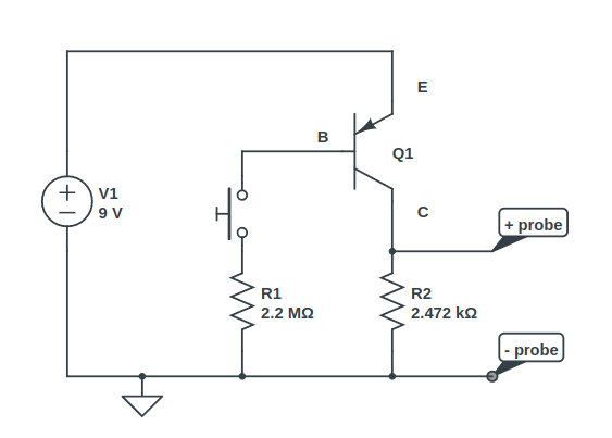
Build the circuit as shown in the first schematic. Set up the transistor so there is nothing connected to the base terminal. The emitter is connected to the supply voltage, while the emitter is pulled to ground through R2.
Measure the leakage by reading the voltage across R2 (between "+probe" and "-probe" in the schematic). Enter that voltage into the Voltage 1 field. Then press the Enter button to save the voltage reading. Some other interesting calculations appear, like the Estimated Base Current (Ib), Estimated Leakage Current (Ileak), and the Perceived hFE.


hFE Measurement
After measuring the leakage reading, close the switch so that R1 is connected to the base. The base should now read close to the supply voltage and the transistor should be conducting. Take the reading from across R2, just like before. Type that value into the field labeled Voltage 2 and click the Get hFE button.
The adjusted voltage is calculated as V2 - V1 (eq. 4). The final hFE value is calculated using equation 5.


Rules for Resistor Values
The tool only allows an integer or decimal value into the resistance fields. In this case, the default unit for R1 is Mega ohms and the default unit for R2 is kilo ohms.
Rules for Voltage Values
The tool only recognizes real numbers for voltage values and does not convert unit suffixes. For example, for 10mV simply write "0.010" into the field.
Meet the Author:

Hi, I'm Dominic. By day, I'm an engineer. By night, I repair and modify guitar effects! Since 2017, I've been independently modifying and repairing guitar effects and audio equipment under Mimmotronics Effects in Western New York. After coming out with a series of guitar effects development boards, I decided the next step is to support that community through content on what I've learned through the years. Writing about electronics gives me great joy, particularly because I love seeing what others do with the knowledge they gain about guitar effects and audio circuits. Feel free to reach out using the contact form!

