

Recently a client reached out asking for an External Switch modification for the Gamechanger Audio PLUS, similar to the Outsource Mod commonly offered for the Electro-Harmonix Freeze. Here’s what they said:
Hi … Would it be possible for you to mod a Gamechanger Audio Plus pedal for an outboard momentary latch switch (silent) like you do the Freeze? I want to install the switch on the guitar, I have someone here to do that. There are a lot of extra jacks that I do not use – especially the wet. I have 2 of these so time is not a problem. I prefer the sound of these to the Freeze and would like to have the trigger both on the pedal and the guitar. Hope this makes sense!
After a little back and forth we finally settled on installing a 3.5mm jack as the input jack for the external switch. The reasoning was to use less internal space, as well as to keep the pedal as stock as possible.
If the external switch takes a 1/4″ plug, then a 3.5mm to 1/4″ adapter is required. Additionally, the external switch needs to be normally open.

As a member of the Reverb Partner Program, eBay Partner Network, and as an Amazon Associate, StompboxElectronics earns from, and is supported by, qualifying purchases.
Disclaimer: Stompbox Electronics and/or the author of this article is/are not responsible for any mishaps that occur as a result of applying this content.
The Gamechanger Audio PLUS Pedal
The Gamechanger Audio PLUS pedal is a common alternative to the popular Electro-Harmonix Freeze pedal for endless sustain. It allows you to smoothly sustain transitions while allowing you to layer them on top of each other.
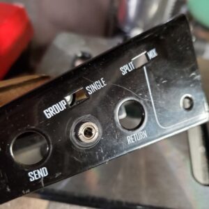
The pedal comes with a slider switch control for toggling between Wet Only output and a Dry+Wet mixed output, which is a common modification requested for the EHX Freeze.
The Trigger Circuit
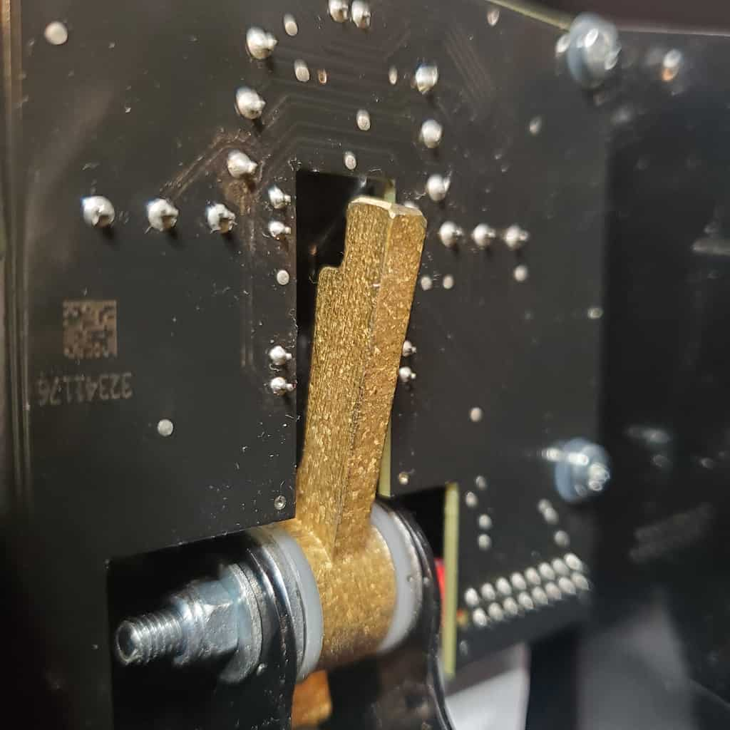
The Gamechanger Audio PLUS uses a piano-like pedal for triggering the sustain of the guitar signal. There are two main positions: half-press and full-press.
The half-press triggers the sampling of the audio input. A full-press adds emphasis to the sustained note by embellishing the sound with more volume and texture.
There are other uses for these two positions, depending on which mode you’re in. Consult the manual for more details.
Triggering the half- and full-press positions is accomplished using an LED and photo-transistor arrangement. There is one notch on the bottom-side of the gold-painted lever. It’s cut in such a way to block one light path before the other, which allows GCA to achieve that half-press/full-press functionality.
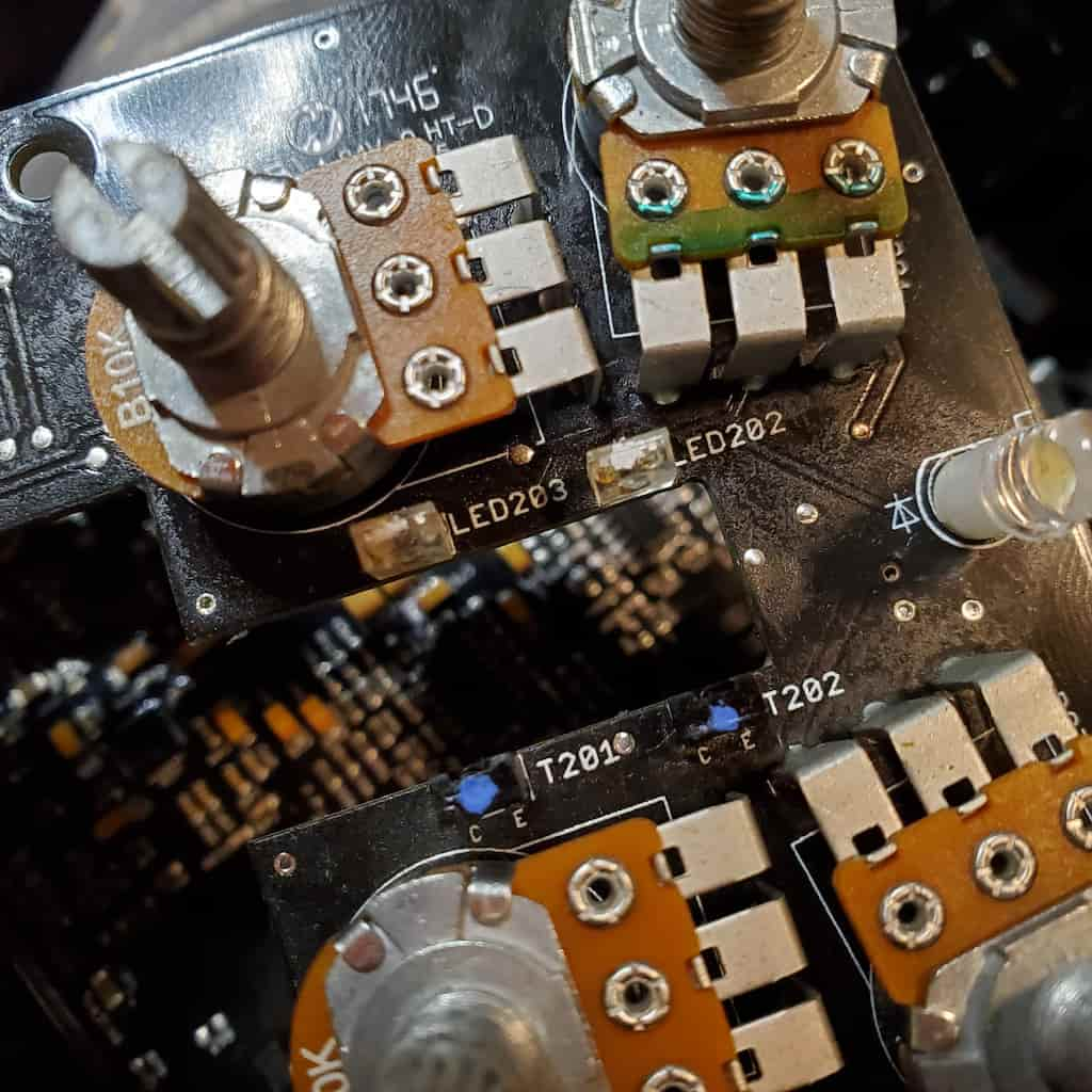
LED202 and LED203 (in the photo above) are always-on, non-visible light sources that shine onto the T202 and T201 photo-transistors, respectively. The processor on the main circuit board detects when the light beams are interrupted and determines whether the pedal is in the half-pressed or full-pressed position.
PLUS Pedal External Switch Modification
The Idea
The idea behind the external switch modification for the PLUS pedal is to simulate the interruption of the beam generated by LED203. The best way I found was to remove LED203’s power source so it stops shining onto the photo-transistor, thus simulating the beam being cut by the gold lever.
Implementing the Modification Circuit
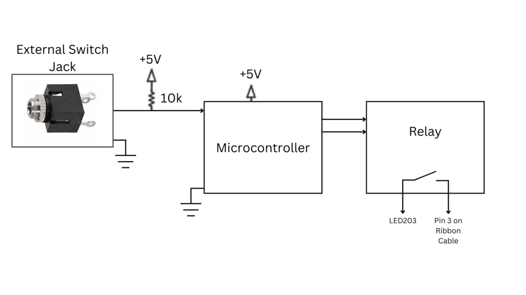
There are three main blocks for this modification: the external switch jack, the microcontroller, and the relay. See below for a simplified block diagram.
Wiring the External Switch Jack
The external switch jack has three lugs: a sleeve connection, a tip connection, and a switched-tip connection. The tip of the external jack intercepts the external switch signal, which routes to an input pin on a microcontroller. That signal is also pulled up by a 10k resistor. The sleeve connection connects to ground.
There’s just one problem: I needed to make sure the pedal works when no external switch was plugged in (i.e. stock mode). That means I needed a “status” input to sense whether or not a plug was inserted into the jack. Usually a ring connection is perfect for this, but the connector I decided to use did not have a ring lug.
Instead, I settled for sensing a “start-up” condition on the input jack by connecting the switched-tip lug to ground.
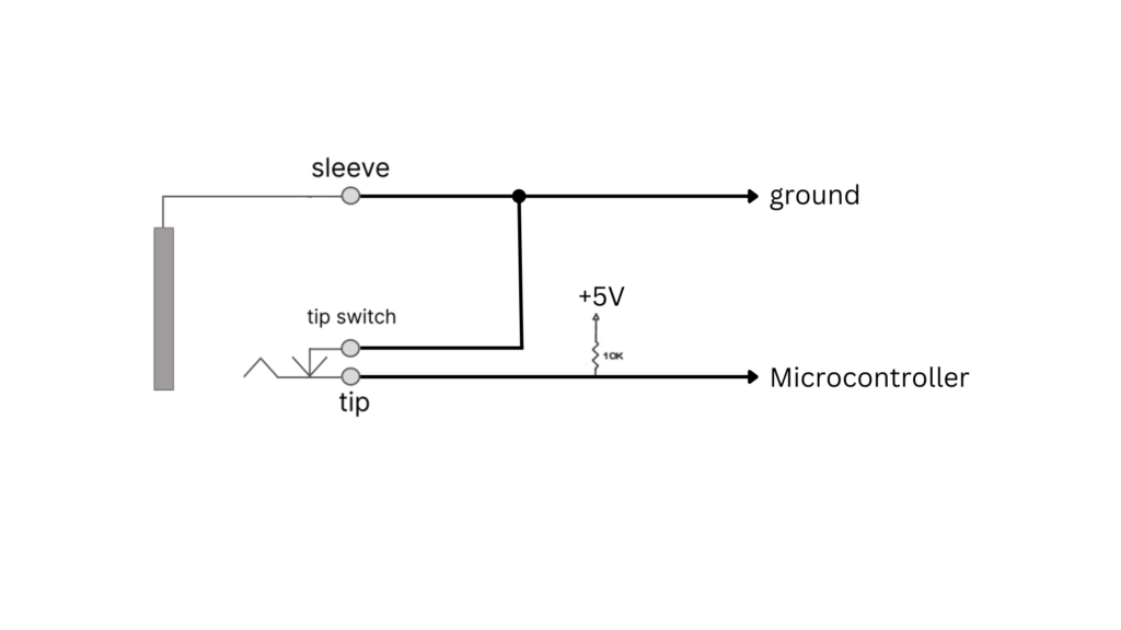
It works like this: the microcontroller starts up when the pedal powers on. First, it looks at the status of the input pin. If a plug is inserted into the connector then the switched-tip disconnects from the tip and the input pin is pulled up to 5V.
On the other hand, if no plug is inserted into the connector, then the tip is grounded through the switched-tip and the input pin is pulled down to zero volts (0V).
The Relay Module
A latching relay was used for this modification. I could have utilized a non-latching relay, but I already built and engineered a circuit and PCB for latching relays, so I decided to use that.
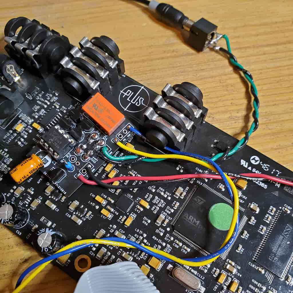
LED203 connects to pin 3 on the ribbon cable connector (verified through a conductivity test on my multimeter). I cut that connection with an X-Acto knife and connected up two wires: one to LED203 and the other to pin 3 on the ribbon cable connector.
The photo below makes it seem like I cut into a neighboring trace, but it’s just a light scratch from when the knife got away from me. If you’re trying this out, be careful and precise.
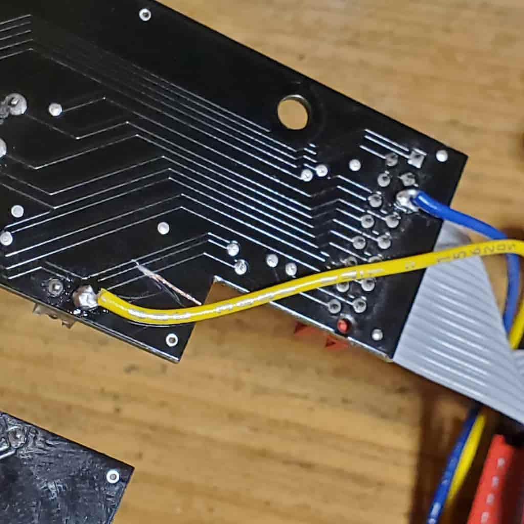
I used the normally closed contact on the relay to replace the connection between LED203 and pin 3 of the ribbon cable.
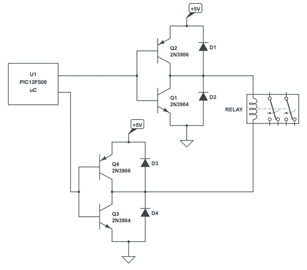
As for the relay coil connections, latching relays require a special circuit configuration. I previously engineered this on a small PCB board a while back. The circuit involves two NPN bi-polar junction transistors (BJTs) and two PNP BJTs. The four diodes are there to protect from back-emf produced by the coil.
Power Wiring
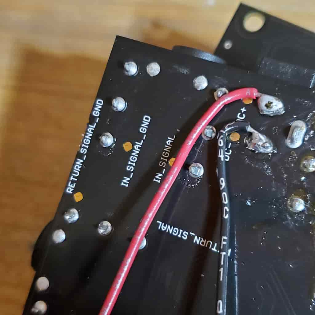
The power came directly from the +9Vdc and ground connection on the stock power connector’s tip and sleeve lugs. A red wire signifies +9V and black signifies ground.
A 100mA TO-92 packaged +5Vdc voltage regulator was used to step the voltage down to the +5V logic level for the microcontroller and relay circuit.
Coding the Microcontroller
And finally: coding the microcontroller. I used a PIC12F509, which requires MPLAB X IDE software. Below is the C program for reference.
Available on request!To load the program into the PIC microcontroller I used the Pickit 3, available from Amazon.
Final Result
Meet the Author:

Hi, I’m Dominic. By day, I’m an engineer. By night, I repair and modify guitar effects! Since 2017, I’ve been independently modifying and repairing guitar effects and audio equipment under Mimmotronics Effects in Western New York. After coming out with a series of guitar effects development boards, I decided the next step is to support that community through content on what I’ve learned through the years. Writing about electronics gives me great joy, particularly because I love seeing what others do with the knowledge they gain about guitar effects and audio circuits. Feel free to reach out using the contact form!
The Tools I Use
As a member of Amazon Associates, Stompbox Electronics earns and is supported by qualifying purchases.


